Sonia Fahmy < fahmy@cse.wustl.edu>
Abstract -Asynchronous Transfer Mode (ATM) switching is not defined in the ATM standards, but a lot of research has been done to explore various ATM switch design alternatives. Each design has its own merits and drawbacks, in terms of throughput, delay, scalability, buffer sharing and fault tolerance. By examining the features of the basic switch designs, several conclusions can be inferred about the design principles of ATM switching, and the various tradeoffs involved in selecting the appropriate approach.
Asynchronous Transfer Mode (ATM) is the technology of choice for the Broadband Integrated Services Digital Network (B-ISDN). The ATM is proposed to transport a wide variety of services in a seamless manner. In this mode, user information is transferred in a connection oriented fashion between communicating entities using fixed-size packets, known as ATM cells. The ATM cell is fifty-three bytes long, consisting of a five byte header and a forty-eight byte information field, sometimes referred to as payload.
Because switching is not part of the ATM standards, vendors use a wide variety of techniques to build their switches. A lot of research has been done to explore the different switch design alternatives, and if one were to attempt to describe the different variations of each, this paper would turn into a book of several volumes. Hence only the major issues are highlighted here, and the various merits and drawbacks of each approach are briefly examined.
The aim of ATM switch design is to increase speed, capacity and overall performance. ATM switching differs from conventional switching because of the high-speed interfaces (50 Mbps to 2.4 Gbps) to the switch, with switching rates up to 80 Gbps in the backplane. In addition, the statistical capability of the ATM streams passing through the ATM switching systems places additional demands on the switch. Finally, transporting various types of traffic, each with different requirements of behavior and semantic or time transparency (cell loss, errors, delays) is not a trivial matter. To meet all these requirements, the ATM switches had to be significantly different from conventional switches.
A large number of ATM switch design alternatives exist, both in the hardware and the software components. The software needs to be partitioned into hardware-dependent and independent components, and the modularity of the whole switch design is essential to easily upgrade the switches.
An ATM switching system is much more than a fabric that simply routes and buffers cells (as is usually meant by an ATM switch), rather it comprises an integrated set of modules. Switching systems not only relay cells, but also perform control and management functions. Moreover, they must support a set of traffic control requirements.
Due to this functional division of an ATM switching system, the remainder of this survey is organized as follows. First, various switching functions and requirements are discussed. Then a generic functional model for a switching architecture is presented to simplify the ensuing discussion. The core of the switch, the switch fabric, will be the main focus of this paper, and thus it is explored in great depth, highlighting the main design categories. Finally, the problems and tradeoffs exposed when analyzing these switch fabric design alternatives are used to draw some conclusions on the major switch design principles.
An ATM switch contains a set of input ports and output ports, through which it is interconnected to users, other switches, and other network elements. It might also have other interfaces to exchange control and management information with special purpose networks. Theoretically, the switch is only assumed to perform cell relay and support of control and management functions. However, in practice, it performs some internetworking functions to support services such as SMDS or frame relay.
It is useful to examine the switching functions in the context of the three planes of the B-ISDN model [3].
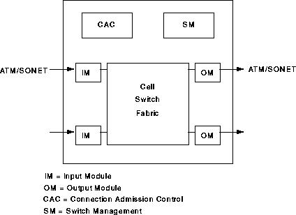
The main function of an ATM switch is to relay user data cells from input ports to the appropriate output ports. The switch processes only the cell headers and the payload is carried transparently. As soon as the cell comes in through the input port, the Virtual Path Identifier/Virtual Channel Identifier (VPI/VCI) information is derived and used to route the cells to the appropriate output ports. This function can be divided into three functional blocks: the input module at the input port, the cell switch fabric (sometimes referred to as switch matrix) that performs the actual routing, and the output modules at the output ports.
This plane represents functions related to the establishment and control of the VP/VC connections. Unlike the user data cells, information in the control cells payload is not transparent to the network. The switch identifies signaling cells, and even generates some itself. The Connection Admission Control (CAC) carries out the major signaling functions required. Signaling information may/may not pass through the cell switch fabric, or maybe exchanged through a signaling network such as SS7.
The management plane is concerned with monitoring the controlling the network to ensure its correct and efficient operation. These operations can be subdivided as fault management functions, performance management functions, configuration management functions, security management functions, accounting management and traffic management. These functions can be represented as being performed by the functional block Switch Management. The Switch Management is responsible for supporting the ATM layer Operations and Maintenance (OAM) procedures. OAM cells may be recognized and processed by the ATM switch. The switch must identify and process OAM cells, maybe resulting in generating OAM cells. As with signaling cells, OAM cells may/may not pass through cell switch fabric. Switch Management also supports the interim local management interface (ILMI) of the UNI. The Switch Management contains, for each UNI, a UNI management entity (UME), which may use SNMP.
The switching system may support connection admission control, usage/network parameter control (UPC/NPC), and congestion control. We will regard UPC/NPC functions as handled by the input modules, congestion control functions as handled by the Switch Management, while special buffer management actions (such as cell scheduling and discarding) are supervised by the Switch Management, but performed inside the cell switch fabric where the buffers are located. Section 5.7 will examine how buffer management is carried out.
It will be useful to adopt a functional block model to simplify the discussion of various design alternatives. Throughout this paper, we will divide switch functions among the previously defined broad functional blocks: input modules, output modules, cell switch fabric, connection admission control, and Switch Management. Figure 1 illustrates this switching model. These functional blocks are service-independent, and the partitioning does not always have well-defined boundaries between the functional blocks. This framework has been developed by Chen and Liu [3]. The greater portion of this paper will be devoted to exploring the different cell switch fabric design alternatives.

The cell switch fabric is primarily responsible for routing of data cells and possibly signaling and management cells as well. Since the remainder of this paper focuses on the cell switch fabric, the next section is devoted to exploring its various components in considerable detail.
Establishes, modifies and terminates virtual path/channel connections. More specifically, it is responsible for:
If the CAC is centralized, a single processing unit would receives signaling cells from the input modules, interpret them, and perform admission decisions and resource allocation decisions for all the connections in the switch. CAC functions may be distributed to blocks of input modules where each CAC has a smaller number of input ports. This is much harder to implement, but solves the connection control processing bottleneck problem for large switch sizes, by dividing this job to be performed by parallel CACs. A lot of information must be communicated and coordinated among the various CACs [3]. In Hitachi's and NEC's ATM switches, input modules - each with its CAC - also contain a small ATM routing fabric. Some of the distributed CAC functions can also be distributed among output modules which can handle encapsulation of high-layer control information into outgoing signaling cells.
Handles physical layer OAM, ATM layer OAM, configuration management of switch components, security control for the switch database, usage measurements of the switch resources, traffic management, administration of a management information base, customer-network management, interface with operations systems and finally support of network management.
This area is still under development, so the standards are not established yet. Switch Management is difficult because management covers an extremely wide spectrum of activities. In addition, the level of management functions implemented in the switch can vary between minimal and complex.
Switch Management must perform a few basic tasks. It must carry out specific management responsibilities, collect and administer management information, communicate with users and network managers, and supervise and coordinate all management activities. Management functions include fault management, performance management, configuration management, accounting management, security management, and traffic management. Carrying out these functions entails a lot of intraswitch communication between the Switch Management and other functional blocks.
A centralized Switch Management can be a performance bottleneck if it is overloaded by processing demands. Hence, Switch Management functions can be distributed among input modules, but a lot of coordination would be required. Each distributed input module Switch Management unit can monitor the incoming user data cell streams to perform accounting and performance measurement. Output module Switch Management units can also monitor outgoing cell streams [3].
The cell switch fabric is primarily responsible for transferring cells between the other functional blocks (routing of data cells and possibly signaling and management cells as well). Other possible functions include:
Each of these functions will be explored in depth in the context of the various design alternatives and principles.
Traffic needs to be concentrated at the inputs of the switching fabric to better utilize the incoming link connected to the switch. The concentrator aggregates the lower variable bit rate traffic into higher bit rate for the switching matrix to perform the switch at standard interface speed. The concentration ratio is highly correlated with the traffic characteristics, so it needs to be dynamically configured. The concentrator can also aid in dynamic traffic distribution to multiple routing and buffering planes, and duplication of traffic for fault tolerance. At the outputs of the routing and buffering fabric, traffic can be expanded and redundant traffic can be combined.
The routing and buffering functions are the two major functions performed by the cell switch fabric. The input module attaches a routing tag to each cell, and the switch fabric simply routes the arriving cells from its inputs to the appropriate outputs. Arriving cells may be aligned in time by means of single-cell buffers. Because cells may be addressed to the same output simultaneously, buffers are needed. Several routing and buffering switch designs have aided in setting the important switch design principles. All current approaches employ a high degree of parallelism, distributed control, and the routing function is performed at the hardware level.
Before examining the impact of the various design alternatives, we need to consider the essential criteria for comparing among them. The basic factors are:
Traditionally switching has been defined to encompass either space switching or time switching or combinations of both techniques. The classification adopted here is slightly different in the sense that it divides the design approaches under the following four broad categories [3]:
For simplicity, the ensuing discussion will assume a switch with N input ports, N output ports, and all port speeds equal to V cells/s. Multicasting and broadcasting will be addressed with the other issues in the next section, so they will be temporarily ignored in this discussion.
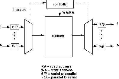
This approach is an output queueing approach, where the output buffers all physically belong to a common buffer pool. The approach is attractive because it achieves 100% throughput under heavy load. The buffer sharing minimizes the amount of buffers needed to achieve a specified cell loss rate. This is because if a large burst of traffic is directed to one output port, the shared memory can absorb as much as possible of it. CNET's Prelude switch was one of the earliest prototypes of this technique, which employed slotted operation with packet queueing [2,7]. Hitachi's shared buffer switch and AT&T's GCNS-2000 are famous examples of this scheme [7].
The approach, however, suffers from a few drawbacks. The shared memory must operate N times faster than the port speed because cells must be read and written one at a time. As the access time of memory is physically limited, the approach is not very scalable. The product of the number of ports times port speed (NV) is limited. In addition, the centralized memory controller must process cell headers and routing tags at the same rate as the memory. This is difficult for multiple priority classes, complicated cell scheduling, multicasting and broadcasting.
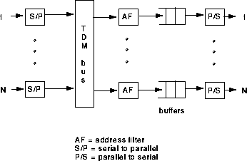
The outputs are modular, which makes address filters and output buffers easy to implement. Also the broadcast-and-select nature of the approach makes multicasting and broadcasting straightforward. As a result, many such switches have been implemented, such as IBM's Packetized Automated Routing Integrated System (PARIS) and plaNET, NEC's ATM Output Buffer Modular Switch (ATOM), and Fore Systems' ForeRunner ASX-100 to mention a few [7,10]. The Synchronous Composite Packet Switching (SCPS) which uses multiple rings is also one of the most famous experiments of shared medium switches [2].
However, because the address filters and output buffers must operate at the shared medium speed, which is N times faster than the port speed, this places a physical limitation on the scalability of the approach. In addition, unlike the shared memory approach, output buffers are not shared, which requires more total amount of buffers for the same cell loss rate.
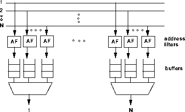
This design has many advantages. As before, all queueing occurs at the outputs. In addition, multicasting and broadcasting are natural, like in the shared medium approach. Address filters and output buffers are simple to implement and only need to operate at the port speed. Since all of the hardware operates at the same speed, the approach is scalable to any size and speed. Fujitsu's bus matrix switch and GTE Government System's SPANet are examples of switches in which this design was adopted.
Unfortunately, the quadratic growth of buffers limits the number of output ports for practical reasons. However, the port speed is not limited except by the physical limitation on the speed of the address filters and output buffers.
The Knockoutswitch developed by AT&T was an early prototype where the amount of buffers was reduced at the cost of higher cell loss [2,7]. Instead of N buffers at each output, it was proposed to use only a fixed number of buffers L for a total of NxL buffers. This technique was based on the observation that it is unlikely that more than L cells will arrive for any output at the same time. It was argued that selecting the L value of 8 was sufficient for achieving a cell loss rate of 1/1 Million under uniform random traffic conditions for large values of N.
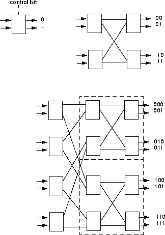
To better understand the composition of banyan networks, consider forming a 4x4 banyan network. Figure 5 shows the step-by-step interconnection of switching elements to form 4x4, and then 8x8 banyan networks. The interconnection of two stages of 2x2 switching elements can be done by using the first bit of the output address to denote which switching element to route to, and then using the last bit to specify the port. 8x8 banyans can be recursively formed by using the first bit to route the cell through the first stage, either to the upper or lower 4x4 network, and then using the last 2 bits to route the cell through the 4x4 network to the appropriate output port.
In general, to construct an NxN banyan network, the nth stage uses the nth bit of the output address to route the cell. For N = 2 to the power of n, the banyan will consist of n = log to the base 2 of N stages, each consisting of N/2 switching elements. A MIN is called self-routing when the output address completely specifies the route through the network (also called digit-controlled routing).
The banyan network technique is popular because switching is performed by simple switching elements, cells are routed in parallel, all elements operate at the same speed (so there is no additional restriction on the size N or speed V), and large switches can be easily constructed modularly and recursively and implemented in hardware. Bellcore's Sunshine switch, and Alcatel Data Networks' 1100 are just a few examples of switches employing this technique.
It is clear that in a banyan network, there is exactly one path from any input to any output. Regular banyans use only one type of switching element, and SW-banyans are a subset of regular banyans, constructed recursively from LxM switching elements.
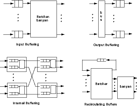
Alternatively, buffers may be placed internally within the banyan switching elements. Thus if two cells simultaneously attempt to go to the same output link, one of them is buffered within the switching element. This internal buffering can also be used to implement a backpressure control mechanism, where queues in one stage of the banyan will hold up cells in the preceding stage by a feedback signal. The backpressure may eventually reach the first stage, and create queues at the banyan network inputs [3]. It is important to observe that internal buffering can cause head-of-line blocking at each switching element, and hence it does not achieve full throughput. Awdeh and Mouftah [23] have designed a delta-based ATM switch with backpressure mechanism capable of achieving a high throughput, while significantly reducing the overall required memory size.
A third alternative is to use a recirculating buffer external to the switch fabric. This technique has been adopted in Bellcore's Sunshine and AT&T's Starlite wideband digital switch [2]. Here output conflicts are detected after the Batcher sorter, and a trap network selects a cell to go through, and recirculates the others back to the inputs of the Batcher network. Unfortunately, this approach requires complicated priority control to maintain the sequential order of cells and increases the size of the Batcher network to accommodate the recirculating cells [3].
As discussed before, output buffering is the most preferable approach. However, banyan networks cannot directly implement it since at most one cell per cell time is delivered to every output. Possible ways to work around this problem include:
The multipath MINs achieve more uniform traffic distribution to minimize internal conflicts, and exhibit fault tolerance. However if cells can take independent paths with varying delays, a mechanism is needed to preserve the sequential ordering of cells of the same virtual connection at the output. Since this might involve considerable processing, it is better to select the path during connection setup and fix it during the connection. Special attention must be paid during path selection to prevent unnecessary blocking of subsequent calls. Widjaja and Leon-Garcia [25] have proposed a helical switch using multipath MINs with efficient buffer sharing. They have used a virtual helix architecture to force cells to proceed in sequence.
From the preceding section, it can be seen that each design alternative has its own merits, drawbacks, and considerations. The general design principles and issues exposed in the last section are analyzed in more detail here.
A fabric is said to be internally blocking if a set of N cells addressed to N different outputs can cause conflicts within the fabric. Internal blocking can reduce the maximum possible throughput. Banyan networks are blocking, while TDM buses where the bus operates at least N times faster than the port speed are internally nonblocking. By the same concept, shared memory switches which can read and write at the rate of NV cells per second are internally non-blocking, since if N cells arrive for N different outputs, no conflicts will occur. Hence, to prevent internal blocking, shared resources must operate at some factor greater than the port speed. Applying this to banyan networks, the internal links need to run square root of N times faster than the highest speed incoming link [7]. This factor limits the scalability and throughput of the switch. Coppo et al. [20] have developed a mathematical model for analyzing the optimal blocking probability versus complexity tradeoff.
Buffering is necessary in all design approaches. For instance, in a banyan network, if two cells addressed to the same output successfully reach the last switching stage at the same time, output contention occurs and must be resolved by employing buffering. The location and size of buffers are important issues that must be decided [7].
There are four basic approaches to the placement of buffers. These basic approaches are illustrated in figure 6. The literature abounds with comparative studies of these, augmented with numerous queueing analyses and simulation results. Uniform random traffic, as well as bursty traffic have been examined. Although each approach has its own merits and drawbacks, output queueing is the preferred technique so far.
Several methods have been proposed to tackle the head-of-the-line blocking problem, but they all exhibit complex design. Increasing the internal speed of the space division fabric by a factor of four, or changing the First-In-First-Out (FIFO) discipline are two examples of such methods.
The number and size of buffers has a significant impact on switch design. In shared memory switches, the central buffer can take full advantage of statistical sharing, thus absorbing large traffic bursts to any output by giving it as much as is available of the shared buffer space. Hence, it requires the least total amount of buffering. For a random and uniform traffic and large values of N, a buffer space of only 12 N cells is required to achieve a cell loss rate of 1/10 to the power of 9, under a load of 0.9.
For a TDM bus fabric with N output buffers, and under the same traffic assumptions as before, the required buffer space is about 90 N cells. Also a large traffic burst to one output cannot be absorbed by the other output buffers, although each output buffer can statistically multiplex the traffic from the N inputs. Thus buffering assumes that it is improbable that many input cells will be directed simultaneously to the same output.
Neither statistical multiplexing between outputs or at any output can be employed with fully interconnected fabrics with N squared output buffers. Buffer space grows exponentially in this case.
If ATM switches will ever replace today's large switching systems, then an ATM switch would require a throughput of almost 1 Tbps. The problem of achieving such high throughput rates is not a trivial one.
In all four switch design techniques previously analyzed, it is technologically infeasible to realize high throughputs. The memory access time limits the throughput attained by the shared memory and shared medium approaches, and the design exhibits a tradeoff between number of ports and port speed. The fully interconnected approach can attain high port speeds, but it is constrained by the limitations on the number of buffers.
The space division approach, although unconstrained by memory access time or number of buffers, also suffers from its own limitations:
Thus the previous discussion illustrates the infeasibility of realizing large ATM switches with high throughputs by scaling up a certain fabric design. Large fabrics can only be attained by interconnecting small switch modules (of any approach) of limited throughput.
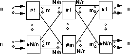
There are several ways to interconnect switch modules. The most popular one is the multistage interconnection of network modules. Figure 7 illustrates the 3 stage Clos (N,n,m) network, which is a famous example of such an interconnection, and is used in Fujitsu's FETEX-150, NEC's ATOM and Hitachi's hyper-distributed switching system. There are N/n switch modules in the first stage, and each is of size nxm. Thus the second stage contains m modules each of size N/nxN/n, and the last stage again has N/n modules of size nxm. Since this configuration provides m distinct paths between any pair of input and output, the traffic distribution can be balanced. Because each cell can take an independent path, cell sequence must be recovered at the outputs. Usually the least-congested path is selected during connection-setup. A new request cannot be accepted if the network is internally congested. Clos networks are strictly non-blocking if there always exists an available path between any free input-output pair, regardless of the other connections in the network. Since in ATM, the bandwidth used by a connection may change at different times, defining the nonblocking condition is not a trivial issue.
The throughput of the Clos network can be increased if the internal links have a higher speed than the ports. In that case, special care must be taken in selecting the size of the buffers at the last switching stage where most of the queueing occurs.
The output buffering principle for Clos networks has been proposed to optimize throughput, where all buffering is located in the last stage of the interconnection network. This places an emphasis on the proper choice of the parameter m. m is usually selected according to the knockout principle previously discussed, which states that for a sufficiently large value of m, it is unlikely for more than m cells to arrive simultaneously for the same last stage module.
Another completely different approach for interconnection is to attempt to find the optimal partitioning of a large NxN fabric into small modules. The set of N inputs can be divided into K subsets, each handled by an N/KxN switch module. The K outputs are then multiplexed. The small switching modules in this case can be implemented as a Batcher sorting network, an expansion network or parallel banyan planes.
Many services, such as video, will need to multicast an input cell to a number of selected outputs, or broadcast it to all outputs. Designing multicasting capability can be done by either adding a separate copy network to the routing fabric, or designing each interconnected switching module for multicasting. Multicasting in different switch design is discussed next.
Implementing the copy network itself has been usually done by banyan networks. The multicast cell is either randomly routed or duplicated at each switching stage, but duplication is delayed as much as possible to minimize resource usage. All duplicates of a cell will have the same addressing information, so the copy network will randomly route the cells. After the copy network, translation tables alter the multicast address to the appropriate output addresses [7].
After observing that the broadcast banyan network is nonblocking if (a) the active inputs are concentrated, (b) there are N or fewer outputs, and (c) the sets of outputs corresponding to inputs are disjoint and sequential, concentration was proposed to be added before a broadcast banyan network. The nonblocking feature of broadcast banyans also holds if the consecutiveness of inputs and outputs is regarded in a cyclic fashion. Byun and Lee [18] investigate an ATM multicast switch for broadcast banyan networks, aimed at solving input fairness problems, while Chen et al. [27] conclude that a neural network method for resolving output port conflict is better than a cyclic priority input access method for multicast switches.
Traffic can be distributed among the parallel fabric planes into disjoint subsets, partially overlapping subsets or it can be duplicated into identical sets. While the first approach provides the least redundancy, each plane carries only a small fraction of the total traffic, so it can be small and efficient. In contrast, duplicating the traffic into identical sets provides the greatest fault tolerance, but the least throughput. Partially overlapping subsets are a compromise.
Composing the routing and buffering fabric of parallel planes enhances fault tolerance, but adding redundancy within each individual fabric plane is still important. Designing fault-tolerant MINs has been the subject of a great deal of study. Banyan networks are especially fault-prone since there is only a single path between each input-output pair. Multipath MINs are more fault tolerant. To add redundancy to banyans, extra switching elements, extra stages, redundant links, alternate links or more input and output ports can be added. These techniques increase fault tolerance by providing more than one path between each input and output, and throughput of the banyan can also increase. Of course, this is at the cost of a more complex implementation and routing. Time redundancy, where a cell attempts multiple passes through the MIN, has also been proposed. A Baseline tree approach has also been investigated by Li and Weng [19]. This approach preserves most of the advantages of MINs, while providing a good performance under high traffic loads in the presence of faults in the switch.
A testing mechanism now needs to be implemented to verify the MIN operation and detect faults. A possible method can be to periodically inject test cells in a predetermined pattern and observe these cells at the outputs to detect the cell pattern. Addition of housekeeping information to the cell header can also aid in discovering cell less, misrouting or delays. Once a fault has been detected, traffic should be redistributed until the fault is repaired. The redistribution function can be carried out by concentrators, or by the MIN itself [3].
The cell switch fabric needs to handle the different classes of ATM traffic differently according to the Quality of Service (QoS) requirements of each. The traffic classes are mainly distinguished by their cell delay and cell loss priorities. Since output queueing was discovered to be the preferred approach, the switch fabric will have multiple buffers at each output port, and one buffer for each QoS traffic class. Each buffer is FIFO to preserve the order of cells within each VPC/VCC, but the queueing discipline must not necessarily be FIFO.
Buffer management refers to the discarding policy for the input of cells into the buffers and the scheduling policy for the output of cells from the buffers. These functions are a component of the traffic control functions handled by the Switch Management. Inside the switch fabric, the queues need to be monitored for signs of congestion to alert the Switch Management and attempt to control the congestion. A performance analysis of various buffer management schemes can be found in the paper by Huang and Wu [24]. They also propose a priority management scheme to provide real-time service and reduce the required buffer size.
Several degrees of delay priority can be associated with each virtual circuit connection. Since this is not part of the ATM cell header, it is usually associated with each VPI/VCI in the translation table within the switch. It can also be part of the internal routing tag associated with each cell within the switch. Of course, cells of the same VCC must have the same delay priority, though they can have different cell loss priorities.
A better approach is the deadline scheduling, whereby each cell has a target departure time from the queue based on its QoS requirements. Cells missing their deadlines might be discarded based on switch implementation and traffic requirements. If service is given to the cell with most imminent deadline, the number of discarded cells can be minimized. A different scheduling scheme divides time into cycles, and takes scheduling decisions only at the start of each cycle, instead of before each cell [3].
In the push-out scheme, cells with CLP=1 are not admitted into a full buffer, while those with CLP=0 are admitted only if some space can be freed by discarding a cell with CLP=1. This scheme has an optimal performance. In contrast, the partial buffer-sharing approach entails that the cells with CLP=0 and CLP=1 can both be admitted when the queue is below a given threshold. When the queue exceeds this threshold, only cells with CLP=0 can be admitted as long as there is buffer space available. This can lead to inefficiency since CLP=1 cells can be blocked even when buffer space is available. This scheme can be designed for a good performance, and its implementation is much simpler than the push-out one. Choudhury and Hahne [22] propose a technique for buffer management that combines the backpressure mechanism with a push-out scheme to achieve a very low cell loss rate.
Buffer management should be able to provide the Switch Management with performance data, congestion information, records of discarded cells, and usage management data for accounting. When congestion is detected, the Switch Management may instruct the buffer management to adjust the cell scheduling and discarding policies. The Explicit Forward Congestion Indication (EFCI) can be triggered, and in this case buffer management must alter the payload type field in the ATM cell header. Explicit rate schemes can also be activated for better congestion control. Most currently available switches only provide EFCI congestion control, such as ForeSystems ForeRunner and ForeThought ASX families [10].
There are numerous different design alternatives for ATM switches, and each has its own merits and drawbacks. By examining the general highlights of each design, several conclusions can be drawn about the design principles of ATM switches, and the various tradeoffs involved in selecting among them.
An ATM switching system is composed of the switch interface, divided into the input and output modules, the connection admission control and Switch Management responsible for connection and OAM functions, and the core of the switch, the cell switch fabric. This has been the main focus of this survey.
The cell switch fabric, sometimes referred to as the switch matrix, may consist of concentration/duplication, expansion/combination and buffer management. Buffer management is quite complicated due to the varying requirements of different QoS classes, which affect the cell scheduling and discarding policies, as well as the congestion control indication. The routing and buffering fabric, however, constitutes the heart of the switch.
The design principles of the routing and buffering fabric were developed after analyzing the main switch design categories, namely the shared memory, shared medium, fully interconnected and space division approaches and their variations. The problem of the speedup factor for shared resources, the contrasting of the types of buffering and the statistical sharing of buffers are only a few of the issues that become apparent when examining the various available designs. In addition, the interconnection of switching modules was discussed, as well as fault tolerance, multicasting and priority considerations.