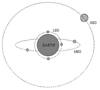
Fig 1. Different satellite constellations
| ATM | Asynchronous Transfer Mode |
| ALE | ATM Link Enhancer |
| BER | Bit Error Rate |
| BS | Base Station |
| CDMA | Code Division Multiple Access |
| DAMA | Demand Assignment Multiple Access |
| DLC | Data Link Control |
| DTH | Direct To Home |
| ES | Earth Station |
| GEO | Geostationary Earth Orbit |
| ISP | Internet Service Provider |
| LEO | Low Earth Orbit |
| LOS | Line Of Sight |
| LNA | Low Noise Amplifier |
| LLC | Logical Link Control |
| MAC | Media Access Control |
| MAN | Metropolitan Area Network |
| MEO | Medium Earth Orbit |
| MSS | Mobile Satellite Services |
| PHY | PHYsical layer of a network model |
| PRMA | Packet Reservation Multiple Access |
| QoS | Quality of Service |
| UPT | Universal Personal Telecommunications |
| VSAT | Very Small Aperture Terminal |
| VCI | Virtual Circuit Identifier |
| WAN | Wide Area Network |
A communication satellite functions as an overhead wireless repeater station that provides a microwave communication link between two geographically remote sites. Due to its high altitude, satellite transmissions can cover a wide area over the surface of the earth. Each satellite is equipped with various "transponders" consisting of a transceiver and an antenna tuned to a certain part of the allocated spectrum. The incoming signal is amplified and then rebroadcast on a different frequency. Most satellites simply broadcast whatever they receive, and are often referred to as "bent pipes". These were traditionally used to support applications such as TV broadcasts and voice telephony. In recent times, the use of satellites in packet data transmission has been on the rise. They are typically used in WAN networks where they provide backbone links to geographically dispersed LAN's and MAN's [Elbert].
Satellite communication channels are characterized by:The received microwave power involved in satellite links is typically very small (of the order of a few 100 picowatts). This means that specially designed earth stations that keep C/N (carrier to noise ratio) to a minimum are used to transmit/receive satellite communications. The front end receiver is the most crucial part of the tranceiver and is a major factor in the overall cost of the satellite ES. It typically employs a large antenna (Gain of a parabolic antenna is propotional to the square of its diameter) and a highly linear, low noise microwave amplifier (LNA) [Berkeley].
Satellite links can operate in different frequency bands and use separate carrier frequencies for the up-link and down-link. Table 1 shows the most common frequency bands. The use of C bands was most common in 1st generation Satellite systems. However this band is already crowded as terrestrial microwave links also use these frequencies. The current trend is towards the higher frequencies of Ku and Ka bands. Attenuation due to rain is a major problem in both of these bands. Also due to the higher frequencies, microwave equipment is still very expensive, especially in the Ka band.
| BAND | UP-LINK (GHz) | DOWN-LINK(GHz) | ISSUES |
|---|---|---|---|
| C | 4 (3.7-4.2) | 6 (5.925-6.425) | Interference with ground links |
| Ku | 11 (11.7-12.2) | 14 (14.0-14.5) | Attenuation due to rain |
| Ka | 20 (17.7-21.7) | 30 (27.5-30.5) | High Equipment cost |
| L/S | 1.6 (1.610-1.625) | 2.4 (2.483-2.500) | Interference with ISM band |
Table 1: Frequency spectrum allocation for some common bands
Modern Satellites are often equipped with multiple transponders. The area of the earth's surface covered by a satellite's transmission beam is referred to as the "footprint" of the satellite transponders. The up-link is a highly directional, point to point link using a high gain dish antenna at the ground station. The down-link can have a large footprint providing coverage for a substantial area or a "spot beam" can be used to focus high power on a small region thus requiring cheaper and smaller ground stations. Moreover, some satellites can dynamically redirect their beams and thus change their coverage area [Tenanbaum].
Satellites can be positioned in orbits with different heights and shapes (circular or elliptical). Based on the orbital radius, all satellites fall into one of the following three categories;

Fig 1. Different satellite constellations
| Type | LEO | MEO | GEO |
|---|---|---|---|
| Description | Low Earth Orbit | Medium Earth Orbit | Geostationary Eart Orbit |
| Height | 100-300 miles | 6000-12000 miles | 22,282 miles |
| Time in LOS | 15 min | 2-4 hrs | 24 hrs |
| Merits |
|
|
|
| Demerits |
|
|
|
Table 2: Salient features of different satellite constellations
Satellites are also classified in terms of their payload. Satellites that weigh in the range of 800-1000 kg fall in the "Small" class, whereas the heavier class is named as "Big" satellites. GEO satellites are typically "Big" satellites, whereas LEO satellites can fall in either class [Elbert].
Satellite channels have some unique characteristics that require special considerations at the DLC (Data Link Control) layer of the OSI model. The satellite links are often referred to as Long Fat Pipes; they represent paths with high bandwidth-delay product. Moreover, since they typically provide a broadcast channel, media sharing methods are needed at the MAC (Media Access Control) sublayer of the DLC. The traditional CSMA/CD (Carrier Sense Multiple Access/Collision Detection) schemes typically used in LAN's cannot be used with satellite channels since it is not possible for earth stations to do carrier sense on the up-link due to the point to point nature of the link. A carrier sense at the down-link informs the earth stations about potential collisions that may have occoured 270ms ago (for GEO). Such delays are not practical for implementing CSMA/CD protocols.
Most satellite MAC schemes usually assign dedicated channels in time and/ or frequency for each user. This is because the delay associated in detecting and resolving multiple collisions on a satellite link is usually unacceptable for most applications. Typical MAC schemes are briefly discussed below [Berkeley] ;
ALOHA : Pure Aloha allows every competing stations to transmit anytime. It has a very low efficiency of 18%. S-ALOHA (Slotted ALOHA) using the satellite broadcasts to synchronize the ground station transmissions to the start of a slot time, can improve the efficiency to around 36%. If the number of ground stations is fixed and small, it may be considered as an option.
FDMA : (Frequency Division Multiple Access) It is the oldest and still one of the most common method for channel allocation. In this scheme the available satellite channel bandwidth is broken into frequency bands for different earth stations. This means that guard bands are needed to provide separation between the bands. Also the earth stations must be carefully power controlled to prevent the microwave power spilling into the bands for the other channels.
TDMA : (Time Division Multiple Access) In this method, channels are time multiplexed in a sequential fashion. Each earth station gets to transmit in a fixed time slot only. More than one time slot can be assigned to stations with more bandwidth requirements. This method requires time synchronization between the (ES) Earth Stations which is generated by one of the ES and broadcast via satellite.
CDMA : (Code Division Multiple Access) This scheme uses a hybrid of time/frequency multiplexing and is a form of spread spectrum modulation. It provides a decentralized way of providing separate channels without timing synchronization. It is a relatively new scheme but is expected to be more common in future satellites.
The ability to use on board processing and multiple spot beams will enable future satellite to reuse the frequencies many time more than today's system. In general, channel allocation may be static or dynamic, with the latter becoming increasingly popular. DAMA (Demand Assignment Multiple Access) systems allow the number of channels at any time be less than the number of potential users. Satellite connections are established and dropped only when traffic demands them.
Long round trip delays and high bandwidth-delay product are the dominating issues that effect the design of DLC layers in satellite data networks. In order to isolate the effect of these undesirable features from higher layers and provide transparent interface with other terrestrial networks, research is continuing for efficient MAC and LLC protocols. Most schemes use a combination of different protocols to achieve higher channel efficiency and make channel allocation highly dynamic. Some of the latest protocols are discussed in the following sections.
The Packet Reservation Multiple Access (PRMA) method is an improved form of TDMA that combines TDMA with the techniques of S-ALOHA. It is intended to be used for mobile satellite links comprising of a BS and a number of MS [PRMA].
A TDMA satellite channel consists of multiple time slots in a framed structure. Each time slot can carry data packets belonging to one of the N users. The assignment of time slots to a channel is not fixed but is handled in real time dynamically. Each data packet carries a VCI (Virtual Circuit Identifier) field that indicates its receiving earth station. Different earth stations can recognize their packets on the down-link broadcast by checking the VCI field in the packet.
At any instant a TDMA frame consists of fixed numbers of reserved and empty slots. This information is broadcast to all ES via satellite broadcasts. When an ES has reserved a slot, the packets are termed as "safe" packets. Whenever a new ES tries to establish a channel, it sends an "unsafe" data packet in one of the available slots. If the packet reaches the destination without collision, the slot is reserved and the ES can transmit "safe" packets. If a collision occours, collision avoidence schemes (for example binary exponential backoff alogarith) are used to resolve the conflicts between the contenders. A user that has no data to send in a reserved time slot, loses its resrvation for that slot. A user may reserve more than one time slots, if required. Figure 2 shows an instance of channel allocation for two simultaneous requests.
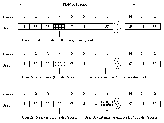
Fig 2. Sequence of steps in a PRMA process
For instance, a LEO satellite environment has small delays and low BER and is therefore "PRMA-compatible" for packetized voice applications. On the other hand, for the same application, a GEO satellite link is "PRMA-uncompatible", due to longer delays and higher BER. A PRMA-uncompatible link would require traditional TDMA to explicitly request time slots for virtual channel setup. Moreover, a ES can interleave a PRMA compatible service within the empty slots of a non-PRMA compatible service. For example non-time critical paging data can use the empty slots of a voice call. This results in improving the channel efficiency of the PRMA technique.
Code Division Multiple Access is a type of spread spectrum commmunication. It was initially used only in military satellites to overcome jamming and provide security to the user [Tenanbaum].
The basic principle of operation is shown in figure 3. Each binary transmission symbol is represented by a spreading code consisting of a zero one sequence. The bit rate of the code is typically much higher than the symbol bit rate and is referred to as the "chip rate". Each user has a unique code that is orthogonal to all the other codes. The resulting signal is obtained by the product of the input data stream and the spreading code. At the receiver, the incoming bit stream is correlated with the receivers's spreading code and user data is retreived. If the data is not meant for that user (i.e. different spreading code), it appears as noise.
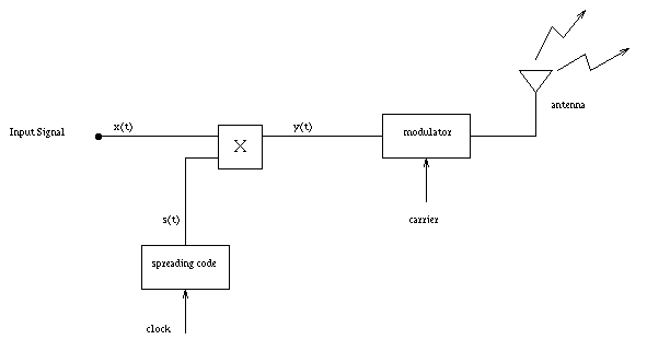
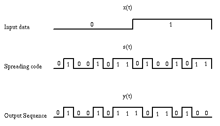
Fig 3. A Simple CDMA process
The main limitation of this method is that the spread spectrum signal of N users increases the noise level. Therefore as the number of users increases, the BER degrades. It is extremely difficult to accurately determine the degradation in system performance with increasing simultaneous users. Still, due to its apparent advantages, most modern satellite systems are employing CDMA as the channel access method.
As mentioned earlier, due to high performance requirements, design of earth station is quite complicated. This increases the costs and the need for maintainence. Very Small Aperture Terminals (VSAT) provides a solution to this problem. The key point in VSAT networks is that either the transmitter or the receiver antenna on a satellite link must be larger. In order to simplify VSAT design, a lower performance microwave transceiver and lower gain dish antenna (smaller size) is used. They act as bidirectional earths stations that are small, simple and cheap enough to be installed in the end user's premesis [Elbert].
VSAT networks are typically arranged in a star based topology, where each remote user is supported by a VSAT. The Earth hub station acts as the central node and employs a large size dish antenna with a high quality transceiver. The satellite provides a broadcast medium acting as a common connection point for all the remote VSAT earth stations. VSAT networks are ideal for centralized networks with a central host and a number of geographically dispersed terminals. Typical examples are small and medium buisnesses with a central office, Banking institutions with branches all over the country, backbone links for an ISP and Airline ticketing system.
The weaker signal from the remote ES is amplified at the satellite acting as a bent pipe and received by the hub ES. Thus the lower gain at the uplink is compensated at the downlink by the high performance Hub ES. The down side of this arrangement is that in case two VSATs need to communicate, two satellite hops are required, since all connections must pass through the hub ES node. The data link supported from the hub to the VSAT is typically slower (19.2 kbps) than that in the reverse direction (512kbps). Figure 4 shows how two VSAT terminals can communicate in a simple VSAT network.
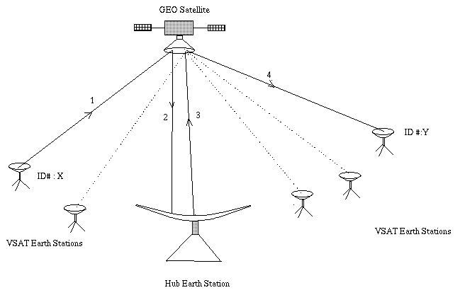
Fig 4. Communication between two VSAT terminals
The most common MAC schemes used on VSAT's are S-ALOHA and TDMA. At the LLC sublayer, a "look back N" protocol with selective reject ARQ (Automatic Repeat reQuest) retransmission strategy is used. The most common implementation uses a transmission window with N=128 packets and the receiver responds with retransmission requests for only erroneous or missing packets. This protocol combined with FEC (Forward Error Correction) produces reliable data transfers while providing low average delays on satellite links. TCP/IP does not fit well in the VSAT scenario, though it can be supported. The most commonly used network protocol on VSAT links is X.25.
Recent advances in satellite technology have enhanced the functionality of the satellites above the bent pipe operation. Modern satellites now employ on-board processing with switching functions. This means that the satellite repeater is capable of demodulation, amplifying in baseband and retransmitting at full power. Thus the basic function of the Hub ES can be eliminated and the satellite can provide full point-point mesh connectivity between VSAT ES with larger bandwidth in both directions. The trend towards multiple high power spot beams in the Ku band would further reduce the VSAT cost and size (60 cm dia antenna dishes). All of the above, combined with the improved hardware and communication schemes will make it possible to provide end user's with several Mbps links.
It is one of the most useful applications of VSAT networks, developed by Hughes Network Systems (HNS) a pioneer in VSAT technology. This service comes with an ISA computer card, a RF dish antenna (2 ft dia) equipped with an LNA, and supporting software. All that is required is an IBM compatible with 486 or higher processor and Windows OS. The VSAT terminal is installed at an open location. A cable runs from the dish antenna and connects to the ISA card inside the PC. The receiver processes of demodulation, decoding and demultiplexing are carried out inside the card. The satellite dish can be aimed at the right angle using a software utility. [DirecPC]
DirecPC supports two kinds of services.
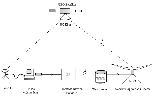
Fig 5. DirecPC service; Sequence of operations
ATM (Asynchronous Transfer Mode) is one of the most promising technology for the information super-highway. Future networks are required to provide broadband integrated services for voice, video and data. ATM is capable of providing the requested QoS (Quality of Service) guarantees typically required by these multimedia services. It is worthwhile to investigate the performance of ATM on Satellite channels.
The basic transfer unit in ATM is a 53 byte unit referred to as a cell. 5 bytes are reserved for the header and the remaining 48 bytes are for the payload. The header field containing the routing, payload type and other network information. It is protected by a single HEC (Header Error Control) byte. This byte allows error detection and corrects all single bit errors in the header.
One of the ATM performance factors is the Cell Loss Ratio (CLR). It depends on the BER of the underlying PHY layer. ATM was designed typically for channels with low BER like fiber, whereas on a satellite channel, the BER is orders of magnitude higher. Moreover, modems used in a satellite channel employ convolutional block coding at the PHY layer for optimum performance. This results in burst error characteristics instead of isolated errors. This means that the self correcting advantage of the HEC in an ATM cell header is lost. The cells with a bad header are discarded which results in significant increase in the CLR.
Research efforts are continuing to find a solution to the problem of bursty noise on satellite channels. One solution is developed by COMSAT [ALE] and is known as the ALE (ATM Link Enhancer). The ALE module is inserted in the transmitting/receiving paths before/after the satellite modems. The ALE performs selective interleaving of the cells before sending them on a satellite channel. This helps in isolating the ATM cells from burst errors. The advantage of the HEC is restored resulting in improved overall performance. COMSAT reports that the CLR improves by several orders of magnitude as a result of using the ALE.
Future satellites will no longer act as "bent pipes"; they would incorporate Inter-Satelite Links, on board switching, data buffering and signal processing. The 1990's have been characterized by the trend of reaching the end user with DTH satellite services. Moreover communication satellites are expected to play a crucial role in providing global PCS (Personal Communication Services). With improving performance in satellite receivers and decreasing cost, satellite receivers equipped with dish antennas are now becoming a household commodity.
Satellites are the obvious choice for universal access for data services as they solve the main hindrance towards this goal, namely distance [Telesat]. Design of modern satellite networks (the so called 3rd generation satellites) is highly influenced by the global trend of user instead of network oriented services. Due to the rapid growth in the cellular market, the telecommunication industry is making large investments in Mobile Satellite Services (MSS) [PCS]. This type of service requires;
Quite a few of the above performance requirements go in favor of "Small" and "Big" LEO satellites. The lower altitude of LEO satellites allows simpler receivers due to smaller attenuation, lesser propagation delays and also allows easy launch (a high altitude aircraft can accomplish the launch). Due to these reasons, LEO satellites are becoming a candidate (though some systems use MEO satellites) choice for providing network services. On the downside, the spot beam property results in constellations that need a large number of LEO satellites (and accompanying ES) for global coverage. Managing and coordinating this large number of earth stations as well as complex handover schemes between satellites is a major drawback for LEO systems. On the other hand GEO satellites can provide both large and narrow footprints with multiple transponders. This combined with the ability to switch data between spot beams are the major factors that go in favour of GEO system [Elbert].
The following list presents some salient features of some of the modern satellite networks that use LEO, MEO as well as GEO satellite constellations
.| IRRIDIUM | |
|---|---|
| Owner | Motorola |
| Satellites | 66, 11/orbit |
| Orbits | 900km, 6 polar orbits |
| Type | Big LEO |
| MAC method | FDMA/TDMA |
| Round trip delay | 10 ms approx. |
| Start of Service | 1998 |
| Services | Voice, Data (2.4 Kbps), FAX, GPS |
| Remarks | Supports Intersatellite links and handoffs during calls |
| On-line Reference | http://www.sat-net.com/L.Wood/constellations/iridium.html |
| INMARSAT M | |
|---|---|
| Owner | Comsat etc. |
| Satellites | 6-20 |
| Orbits | 36000 km |
| Type | GEO |
| MAC method | FDMA |
| Round trip delay | 500 ms |
| Start of Service | 1993 |
| Services | Voice, Data (2.4 Kbps), FAX, Telex |
| Remarks | Allows a 6.4Kbps voice channel, suitcase terminal |
| GLOBALSTAR | |
|---|---|
| Owner | Loaral, Qualcomm |
| Satellites | 48 (8 spares) |
| Orbits | 1400 km, inclined |
| Type | Big LEO |
| MAC method | CDMA |
| Round trip delay | 10 ms approx. |
| Start of Service | 1997 |
| Services | Voice, Data (9.6 Kbps), FAX Location services |
| Remarks | No Satellite handovers, elliptical spot beams |
| On-line Reference | http://www.globalstar.com/ |
| TELEDESIC | |
|---|---|
| Owner | Bill Gates, Craig McCaw |
| Satellites | 840 |
| Orbits | 700 km |
| Type | small LEO |
| MAC method | ATDMA, FDMA, SDMA |
| Round trip delay | 8 ms approx. |
| Start of Service | 2002 |
| Services | Voice, Data upto 2Mbps |
| Remarks | Phased array antennas, installation costs - US $9,000 !! |
| On-line Reference | http://www.sat-net.com/L.Wood/constellations/teledesic.html |
| ODYSSEY | |
|---|---|
| Owner | TRW |
| Satellites | 12 |
| Orbits | 10370 km |
| Type | MEO |
| MAC method | CDMA |
| Round trip delay | 120 ms approx. |
| Start of Service | 1999 |
| Services | Voice, Data (9.6Kbps), FAX, GPS |
| Remarks | No handover, steering antenna eliminates spot beam handover |
| On-line Reference | http://leonardo.jpl.nasa.gov/msl/QuickLooks/odysseyQL.html |
| ICO | |
|---|---|
| Owner | INMARSAT, Hughes |
| Satellites | 10, 2 spares |
| Orbits | 8-10000km |
| Type | MEO |
| MAC method | TDMA |
| Round trip delay | 200 ms approx. |
| Start of Service | 2000 |
| Services | Voice, Data (2.4Kbps), FAX, GPS |
| Remarks | 4500 telephone channels per satellite |
The role of satellites is changing from the traditional telephony and TV broadcast services to user oriented data services. This trend is expected to continue in the future. Due to this reason, 3rd generation MSS will use smart satellites that will incorporate functions such as switching, buffering and beam switching in addition to signal reproduction. Satellite data services on existing GEO satellite systems, like VSAT, will continue to compete with the terestrial options such as Telephone line and Fiber links. Small and large LEO constellations are expected to become a candidate in the cellular market. At the same time the popularity of GEO systems is not expected to diminish. In order to meet the increasing demand for real time traffic, channel access and link layer protocols will have to be optimized to ensure smooth operation over the satellite channel. TDMA and CDMA appear to be two of the stongest candidates for the MAC protocol. The evolution of satellite technology alongwith the fixed and mobile terrestrial communications is expected to merge into Universal Personal Telecommunications (UPT).
* Indicates excellent references on the topic of Satellite Data Networks.
http://www.inmarsat.org/inmarsat/low_band