| Rahav Dor, (A paper written under the guidance of Prof. Raj Jain) |
Download |
Wireless Sensor Networks (WSN) are becoming prevalent and represent the next great change occurring to the Internet and our living spaces. WSN are used in the medical field, smart home and smart grid initiatives, sports training, forestry and wildlife monitoring, and numerous other disciplines. WSN deployments are expected to work for long durations on scarce energy supply and stay reliable with no maintenance. To allow WSN applications to optimize their energy consumption, reliability, or throughput this paper studies the performance characteristics of two MAC protocols, namely RI-MAC and BoX-MAC.
| Acronym | Definition |
|---|---|
| BoX-MAC | MAC protocol based on the earlier B-MAC and X-MAC |
| IPI | Inter Packet Interval ( ) |
| LPL | Low Power Listening |
| MAC | Media Access Control |
| OSI | Open Systems Interconnection |
| Packet Delivery Ratio | Packet Delivery Ratio (%Reliability) |
| QoS | Quality of Service |
| RI-MAC | Receiver Initiated MAC |
| RMA | Reconfigurable MAC Architecture |
| THR | Throughput |
| WSN | Wireless Sensor Networks |
The upward trend in wireless communication caused researchers to envision and develop a plethora of Medium Access Control (MAC) protocols. However, it is often not clear which protocol should an application us for higher reliability, lower energy consumption, or specific throughput demand. Because WSN are deployed in remote areas, on bridges and building in hard to reach places, and are expected to operate with close to zero maintenance – it is important that we will be able to optimize for given application requirements. This paper makes yet another step towards this goal.
We are literally seeing the world of computer-to-computer and people-to-computer communication change in front of our eyes. Communication literally went from almost exclusively wired networks to wireless in less than a decade and in the last couple of years, we have been seeing increasing interest in connecting smart phones and wireless sensors for various mobile sensing applications. A study by CISCO [Evans2011] shows that the Internet of Things is not a futuristic event, it has already arrived. Evans report show that in 2010 we already had more wireless devices connected to the Internet than people living on the planet and he predicts that by 2015, devices will exceed human population by 3.47 to 1.
Until recently Wireless Sensor Networks (WSN) were mostly stationary, But now, with the desire to connect them to mobile devices they face new research and technological challenges. When WSN goes mobile it faces dynamic environments where both the ambient wireless conditions and application requirements are frequently changing. Applications such as fall detection, vital sign monitoring, assisted living, activity recognition, personal health and fitness, terrestrial and marine wildlife monitoring – must all be mobile to be useful. The use of non-WSN technology (such as smart phones alone) is not practical for at least two reasons: (1) The battery life of a smart phone is a day or two, while the expectations from a WSN is measured in months or years. (2) Smart phones do not have (yet) all of the desired sensing modalities. The fusion of a smart phone and a network of sensors marshal opportunities for novel and exciting applications, but as we alluded to above, this brings about new challenges for WSN that need to be addressed.
The first challenge is the dynamics of the operating environment as the user moves through the world, mostly due to the varying ambient interference from external sources. For example, at homes, Bluetooth devices, our own and our neighbors’ Wi-Fi access points, and our microwave – all generate high interference that interact with WSN. This interference is more orderly in office buildings; and outdoors mobile WSN will experience it to a lesser effect [Sha2011]. Therefore a WSN that moves from home, to the drive to work, and into an office will go from very noisy, to varying degrees of clean environments, and into an orderly interference levels. To be able to operate for months or years, a WSN must adapt the protocols it used to save energy. We must know which protocols handle noisy environments better than others, possibly at the expense of higher energy, but there is no need to use such protocols when the interference levels are low.
Second, application throughput needs may change when the sensing scenario changes and the amount of data that a WSN carries is subject to spontaneous changes. In wireless health and assisted living applications for example, the wireless sensors may be emitting a low rate of data when the person is in a healthy state. In this condition, monitoring only the heart rate and blood oxygenation may be sufficient. A typical data rate for this sensing scenario is four bytes per minute. However, if the person’s clinical condition changes it will be required to send a real time ECG. The data rate for this sensing scenario should be 750 bytes per second according to the long standing American Heart Association recommendation for ECG monitoring, which recommend digitization in a frequency of 500 Hz with a resolution of 12 bits [AHA2009].
Responding to a medical condition is not just a throughput Quality of Service (QoS) requirement. The reliability requirement will most certainly change as well. While it may be reasonable to lose a transmission every now and then during clinically stable periods, it may not be that acceptable during imminent clinical deterioration. Some MAC protocols were designed to enable highly reliable transfer of data but they consume large amount of energy and as argued earlier there is no reason to use them when it is not needed.
We conclude by noting that WSN are likely to meet ambient and QoS conditions that will demand optimizing along more than one dimension. WSN will meet an environment in which it will be wise to have both high reliability and high throughput, and some environments will offer prudent opportunities to energy saving. But to address these encounters and opportunities the community needs to clearly understand what are the choices for MAC protocols selection.
In this paper we present a performance study of two of the most prominent MAC protocols in use today: BoX-MAC [Moss2008] and RI-MAC [Sun2008]. We measure the Energy consumption, Reliability, and Latency under varying ambient noise levels, application data rate (throughput) requirements, and the two protocols under study.
The rest of this paper is organized as follows: We will provide background on the OSI model and MAC protocols in the section titled MAC protocols. In the Even the playing field section we will explain the platform on which we performed our experiments. Related art goes over other efforts that are close or provide relevant information to our project. The Experimental design section defines the system under study, the services provided by the system, the metrics, and the factors and their levels. Evaluation technique articulates how each response measure was obtained or calculated. Conducting the experiments section holds the data and results of the three experimental designs we followed. We summarize what we have learned in the Conclusions section. Finally, Future work outlines how we are planning to proceed.
Open Systems Interconnection [OSI1980] defines computer-to-computer communication as having seven (or more modernly five) layers. See Table 1: . Each layer abstracts the details of various mechanisms that a packet (a piece of data) traveling from one computer to another goes through. These abstraction layers (at least by the OSI plan) allow for the replacement of one layer with an updated version of its services.
| Layer | ||||
|---|---|---|---|---|
| Location | Data unit | Number | Name | Function |
| Host | Data | 7 | Application | Whichever the application functionality is |
| 6 | Presentation | Not in use | ||
| 5 | Session | Host to Host communication, managing sessions between applications | ||
| Segments | 4 | Transport | End-to-End connections, reliability and flow control | |
| Media | Packet | 3 | Network | Path determination and logical addressing |
| Frame | 2 | Data link | Physical addressing, Channel access control | |
| Bit | 1 | Physical | Media, signal and binary transmission | |
The MAC protocol is a part of layer 2, the data link layer. The data link layer is responsible for transferring frames between networks hosts. The MAC provides physical addressing and channel access control mechanisms (access control allows several hosts to communicate over shared medium).
Research efforts of the last few years created a multitude of MAC protocols for Wireless Sensor Networks (WSN). Many of these MACs were designed and optimized for low latency, high throughput, power consumption, or robustness to interference. However, none of the existing protocols deliver optimal performance in all desirable attributes under all conditions. For instance, sender initiated low-power listening (LPL) protocols such as the BoX-MAC are efficient in clean environments but suffer high power consumption due to false wake ups in noisy environments [Sha2013]. Receiver-Initiated MACs are more resilient to interference, but may incur higher overhead in clean environment since they periodically transmit probing packets. This is particularly pronounced when the data rate is low. Similarly, while TDMA protocols are suitable for high data rates applications by avoiding channel contentions, CSMA/CA protocols incur less overhead and shorter latency in low data rate.
To the best of our knowledge though, there is no study (grounded with statistical methods or not) that compared MAC protocols as a collection of available choices, a void that our paper is trying to start satisfying. The MAC protocols we are going to study are prominent within the WSN community, namely: BoX-MAC which now comes standard with the source code for TinyOS [TinyOS], and RI-MAC.
[Moss and Levis] presented two new MAC protocols named BoX-MAC-1 and BoX-MAC-2 in 2008. These protocols reached beyond the abstraction layer and incorporated link-layer (where the MAC protocol lives) information into the physical-layer (just below where the MAC protocol lives), and physical-layer information into the link-layer. The result reported in the paper show that these protocols save up to 50% energy and yield up to 46% more throughput compared to previously used protocols XMAC and BMAC. BoX-MAC comes standard today when you download TinyOS, one of the two available open source operating systems for WSN. The second operating system that is prominent today is Contiki [Contiki]. It comes standard with CSMA, which is beyond the scope of our paper at this time.
The Receiver Initiated MAC protocol was introduced by [Sun2008]. “RI-MAC attempts to minimize the time a sender and its intended receiver occupy the wireless medium while they are trying to find a rendezvous time for exchanging data”. The paper reports that this approach yields higher throughput, better reliability, and power efficiency than an asynchronous duty cycling approach of a protocol named X-MAC.
Beyond the need for a comparison study that will allow applications to optimize their performance for energy, reliability, data throughput, or a mixture of those parameters – it would really be beneficial to have an infrastructure that will allow researchers to perform such studies on a common hardware platform. So far, TinyOS or Contiki, come with a monolithic MAC protocol that is compiled with the OS and is fixed during its operation. A different MAC protocol can be used, but the most typical way of changing to a new one is by recompiling the OS code.
An infrastructure that allows for dynamic MAC protocol switching will enable researchers not only to continue our study, or to repeat each other’s experiments, but will also allow applications to enjoy the result of such studies by allowing them to dynamically switch MAC protocols in real-time to match varying conditions.
This is exactly what we have developed in another research project. We have replaced the single MAC protocol with a Reconfigurable MAC Architecture (RMA). This platform enabled us to conduct comparison studies in a fair way, not needing to account for the performance of different hardware platforms and different radios.
Reconfigurable MAC Architecture (RMA) is a replacement for the monolithic MAC that is part of any link layer today. Figure 1 shows its architecture diagram. RMA was designed with the following ideas in mind:
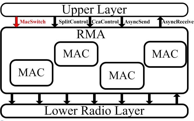
RMA serves as a container for multiple MAC protocols, which are available to applications running on the system in real time. The Upper and Lower layers provide a unified set of interfaces to any OS service that needs a MAC service. Efforts have been taken to make these interfaces similar to what services will be typically requested from a MAC protocol (e.g. AsyncSend is used for sending packets, AsyncReceive is used for receiving frames). In red we see the only new command, namely MacSwitch, which can be ignored, with the behavior defaulting in this case to using a single MAC protocol. At this time RMA has been implemented as part of TinyOS 2.x, but we believe its architecture and design principles are applicable to other OS as well.
Recently, [Marco2012] proposed, designed, and implemented pTunes, a framework for runtime adaptation of MAC protocol parameters. pTunes allows applications to specify their requirements in terms of network lifetime, end-to-end reliability, and end-to-end latency. It then tunes the fine grain parameters of the MAC protocol. While this innovative approach is a very important research contribution, how parameters are tuned is hidden from the users. In this paper our focus is on exposing the operating characteristics and explicitly reporting which parameters affect a desired response.
To be able to evaluates the interaction between several protocols at the MAC and other network layers [Malesci2006] measured their performance in terms of end-to-end throughput and reliability. This work accounts for the limited data available regarding the interactions between layers of the OSI stack.
In his paper [Kuntz2009] showed that there is a large gap between application requirements and the low-level MAC protocol operation, and (Meier) demonstrated that this can lead to performance that is not on par with application needs.
In his CSE 567M final project [Patney2006] conducted a survey on Performance Evaluation Techniques for Medium Access Control Protocols.
In this section we describe the system we are going to study, what services the system provides, and we are going to articulate what metrics we are going to use to study system's behavior (response). A concise explanation and characteristics of the factors that can affect, and the ones we are interested in learning about, will be given.
The system under study is MAC protocols, which are part of the link layer (OSI layer 2). The purpose of the study is to gain initial knowledge of which factors affect the performance the two MAC protocols we intend to study.
The services offered by the system under study is sending and receiving frames between wireless devices. The MAC provides addressing and channel access control mechanisms that allow multiple network hosts to communicate over shared medium (taking care of potential collisions). There are two main services that are exposed to users of a MAC protocol, namely Send and Receive. There are also hidden services that are performed automatically (without explicit request of a MAC protocol user); those are physical addressing and trying to prevent collisions of packets that are about to traverse a common medium (this can be a copper wire for example or the airways between two hosts).
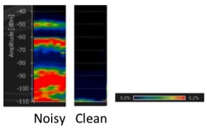
Noise will be introduced into the environment by taking advantage of the fact that WSN networks use the same radio frequency and channels as WiFi networks. We define a noisy environment to be 3 meters away from a WiFi router, and Clean environment as 20 meters away from a WiFi router while communicating on a channel that is not used by any other nearby communication or interference-generating device (such as a microwave). The left image in Figure 2, shows a Noisy environment and the right figure shows a Clean environment. The y-axis in this figure is the raw power of the transmission and the color is the ratio that such level of interference was measured in the location.
At different times, applications need to transfer different amount of data. Many sensor based WSN need data only every 1 or 5 minutes. For example, since temperature does not change frequently a house thermometer need not send its current reading more often that every 5 minutes. This rate may be too low for the two level initial study we want to conduct; so we will set the minimum throughput demand at 2 packets/second. Other applications, at certain points of their operation may require much higher rates. In reality the current maximum rate for some WSN protocols is 100 packets/second. Since we do not want to operate beyond the knee capacity [JainBook] we therefore set the second level that we will measure to 50 packet/second.
Two protocols will be studied in this paper, BoX-MAC that comes as the standard TinyOS protocol today, and RI-MAC that has completely different operation/logic. We believe that this difference in the approach (logic) that those two protocols take will provide for an interesting study.
The three factors and their levels are summarized Table 3.
| Level -1 | Level 1 | ||||
|---|---|---|---|---|---|
| Factor | Symbol | Description | Value | Description | Value |
| Noise | A | Clean environment | 20 m. | Noisy environment | 3 m. |
| Throughput | B | Low | 2 packets/s. | High | 50 packets/s. |
| Protocol | C | BoX-MAC | RI-MAC | ||
We will study the effect that the three factors specified above have on the following response variables
The parameters that can affect the system performance are
In this study the two sources of noise are accumulated into a single noise factor. People activities and location on the body is ignored, the devices will be stationary in all experiments and not worn by people.
The two MAC protocols were authored as RMA components. We will instrument the code to output the duration the radio is active as a proxy for energy consumption. Since the sensor is not doing anything else during the experiment and the CPU time is negligible when compared to the radio energy consumption this would be a good approximation of energy usage. Note that even though this is not an exact measure of the Ampere-hours consumed by the application, all MAC protocols in these experiments are going to be subject to the same offset, keeping our evaluation technique non-biased. The equation which we used to calculated the energy consumption appear is:
where 1.8 is in Volts, 19.7 and 0.426 is the current consumption in mA, timeon and timeoff is the time the radio is ON or OFF respectfully, and T is the period. All of our experiments used a period of 10 seconds.
Reliability is calculated by the ratio called PDR (Packet Delivery Ratio). Each PDR value is calculated over 10 seconds time window:
We define Latency as the time difference between when a packet is sent, to the time it was received. If we let TS be the time a sender sends the packet and TR be the time when a receiver received the packet, then:
Note that if a packet is lost the latency will be skewed. Assuming that a second packet will soon we send, then the latency will be at least 2 times of its expected value. Since the network is not subject to harsh conditions, this is not a great concern, but will need to be addressed if we will decide to continue the study into harsher interference levels or above the knee throughput demands (which may affect the reliability).
We design 2kr=233 experiments, studying the factors' affect on three system responses we are interested in:
We prepare a sign table for the factors (Effects) and all interactions. The three measured responses y_i1, y_i2, and y_i3, measured in [mW] are reported in the table and the mean y¯ is calculated.
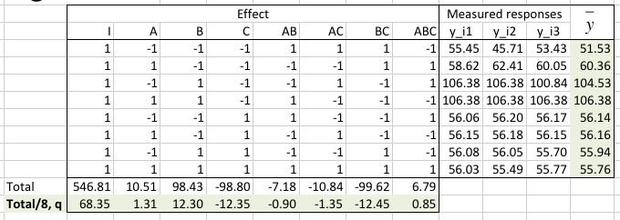
The average q0 and the effect of each factor or factors-interaction appear in the q vector on the last row of the table.
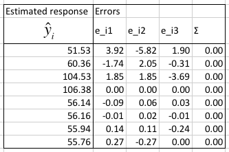
We calculate the modeling errors, make sure that their sum is 0, and calculate the predicted response given the factors from the q vector.
Next we calculate the allocation of variation and determine how important each factor is (the percent of the model it explains). We also calculated the standard deviation of errors, s_e, and the standard deviation for the factors, s_qi.
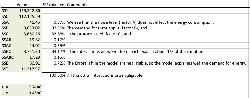
We see that the application demand for throughput (factor B), the protocol used (factor C) and the interaction between them almost equally affect the energy consumption. We are happy to see that the errors left in the model are negligible (0.72%), which means that the model is sound.
In order to know if the effects are statistically significant we calculate a 90% confidence interval for each of them. For 90% confidence level, α=0.10. The degrees of freedom equal
With these values we calculated the confidence intervals [mW]. We see that all of them are statistically significant:
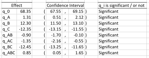
All of the effects turn out to be statistically significant, but we already know that only factors B, C, and their interaction are important (as can be seen in the %Explained calculation). We like elegant models, so we model the energy consumption of a WSN only with the important and significant factors:
Note that this model offers very interesting observations. To a good approximation at low throughput (xB = -1) the model becomes 68 + 12(-1) - 12xC - 12(-1)xC = 68 - 12 - 12xC + 12xC = 68 - 12 = 56. So at low throughput the protocol cancels from the model, it just does not matter.
If we solve the equation exactly, then at low throughput we will have 68 + 12.3(-1) - 12.35xC - 12.45(-1) xC = 55.7 - 12.35xC + 12.45xC = 55.7 + xC(-12.35 + 12.45) = 55.7 + 0.1xC. This suggests that at low throughput BoX-MAC will require a little less energy (than it would require at high throughput).
Another observation is that when the protocol is RI-MAC (xC = 1) the model becomes 68 + 12xB - 12(1) - 12xB(1) = 68 - 12 = 56. Now the throughput cancels from the model. This means that RI-MAC will consume the same amount of energy regardless of the throughput demand. This makes complete sense because of the how a receiver and sender coordinate the transmissions rendezvous time.
At high throughput BoX-MAC will consume 68.35 + 12.3(1) - 12.35(-1) - 12.45(1)(-1) = 68.35 + 12.3 + 12.35 + 12.45 = 105.45 mW.
We summarize these observations as follows. The mean energy consumption is about 68 mW. At low throughput BoX-MAC will require a little bit less energy than RI-MAC. RI-MAC will stay constant at all throughput demands. At high throughput BoX-MAC will consume about 105 mW.
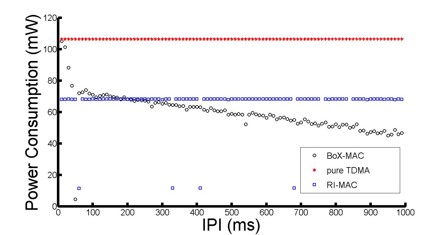
Let's verify these observations with a brief digression beyond the experimental design. We perform 50 experiments, varying the IPI (since throughput = 1/IPI, the left side of the x-axis is high throughput and the right side is low). We were ecstatic to see the predictive power of the model. As can be seen in the next plot RI-MAC is constant, BoX-MAC requires less energy at low throughput (right side of the plot) and this value is very close to the predicted 56 mW. At high throughput BoX-MAC energy consumption increases to the predicted 105 mW.
We conclude using visual tests to make sure that the model is valid. We start by verifying that the modeling assumption of independent errors is correct. Plotting the Residuals vs. the Predicted response of the system will show us if this assumption is correct.
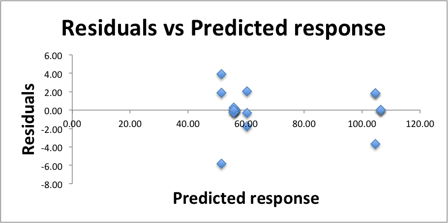
With no apparent trend we conclude that the errors are indeed independent.
To see if the errors are normally distributed we prepare a Q-Q-plot.
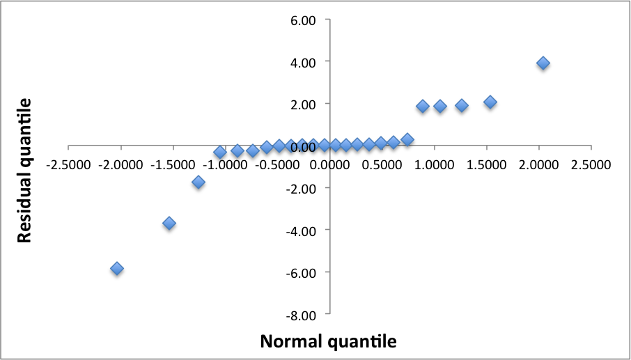
The downward and upward poll of the left and right ends of the q-q-plot suggests that the distribution has longer tails at both ends. The stretching of the left and right edges of the plot to the sides suggests that the distribution is also has a higher peak than a Normal distribution. Despite the fact that this indicates that the residuals are not normally distributed, we decide that given the other positive indicators the model may have good predictive power, and it provides good insight into the system behavior. An experiment with a higher r value should be conducted to further investigate the underlying behavior.
The three measured responses y_i1, y_i2, and y_i3, in % reliability, or PDR, are reported in the table and the mean reliability y¯ is calculated.
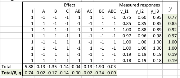
The average q0 and the effect of each factor or factors-interaction appear in the q vector on the last row of the table.
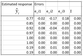
In the next table we estimate the modeling errors, make sure that their sum is 0, and calculate the predicted response given the factors from the q vector.
We calculate the allocation of variation and determine how important each factor is (the percent of the model it explains). We also calculated the standard deviation of errors, s_e, and the standard deviation for the factors, s_qi.
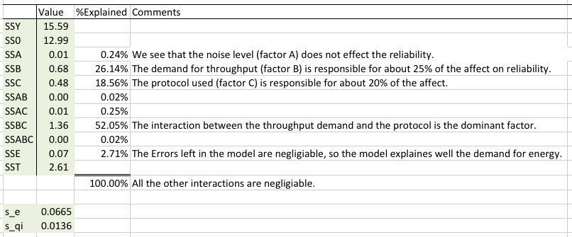
We see that the application demand for throughput (factor B) is responsible for 26.14% of the effect on the system. The protocol used (C) is responsible for 18.56%. And the interaction between these two factors is responsible for 52.05%. It is very surprising that the interactions account for more than the factors themselves. We are happy to see that the errors left in the model are negligible (2.71%), which means that the model is sound.
In order to know if the effects are statistically significant, we calculate a 90% confidence interval for each of them. For 90% confidence level, α = 0.10. The degrees of freedom equal
With these values we calculated the confidence intervals in percent reliability (PDR):
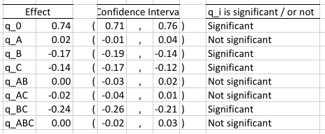
The external noise level (factor A) turns out to be not statistically significant. In the allocation of variation we already have seen that it is also not an important factor. Also not statistically significant and not important are the AB (noise x throughput) and AC (noise x protocol) interactions. The third level interactions ABC also not significant. It turns out that the interaction between the demand for throughput and the choice of protocol, an interaction that was shown earlier to be responsible for more than 50% of the response is also statistically significant. Hence it is an important parameter to consider for systems that would like to have high reliability. The demand for throughput and choice of protocol by themselves are also statistically significant. Armed with this information we model the system with the equation:
We interpret the model as follows. The mean reliability is 74%. If the protocol in use is BoX-MAC (xC = -1) then a low throughput demand will increase the reliability by -0.17(-1) - 0.14(-1) - 0.24(-1)(-1) = 0.17 + 0.14 - 0.24 = 0.07 or 7%. And if the protocol in use is RI-MAC (xC = 1) then a low throughput demand will increase the reliability by -0.17(-1) - 0.14(1) - 0.24(-1)(1) = 0.17 - 0.14 + 0.24 = 0.27 or 27%. So at low throughput RI-MAC is more reliable. If the protocol in use is BoX-MAC, then a high throughput demand will increase the reliability by -0.17(1) - 0.14(-1) - 0.24(1)(-1) = -0.17 + 0.14 + 0.24 = 0.21 or 21%. And if the protocol in use is RI-MAC, then a high throughput demand will lower the reliability by -0.17(1) - 0.14(1) - 0.24(1)(1) = -0.17 - 0.14 - 0.24 = -0.55 or 55%. So at high throughput BoX-MAC is a much better protocol and RI-MAC should be avoided. This is a very important result that we intent to investigate in the future.
The mean reliability is 74%. RI-MAC is more reliable at low throughput demand. It will increase the reliability by 27% over the mean, or 20% higher than BoX-MAC. At high throughput demand BoX-MAC will provide an increase of the reliability by 21% over the mean. RI-MAC will lower the reliability by 55% and should be avoided.
We conclude by performing visual tests to make sure that the model is valid.
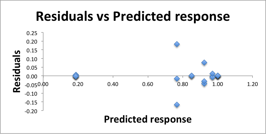
There is some worrisome range of errors at about 0.80 reliability, but no trend in the residuals in general. Because the residuals are small compared to the predicted responses we are approve of this test for the independence of errors.
To see if the errors are normally distributed we prepare a Q-Q-plot.
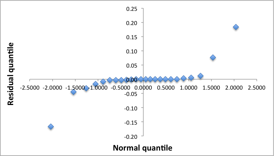
The downward and upward poll of the left and right ends of the q-q-plot suggests that the distribution is not normal.
The three measured responses y_i1, y_i2, and y_i3, in [ms] are provided in the table.

The average q0 and the effect of each factor or factors-interaction appear in the q vector on the last row of the table.
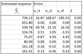
In the next table we estimate the modeling errors, make sure that their sum is 0, and calculate the predicted response given the factors from the q vector.
We calculate the allocation of variation and determine how important is each factor (the percent of the model it explains). We also calculated the standard deviation of errors, s_e, and the standard deviation for the factors, s_qi.
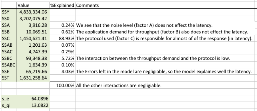
It was rewarding to see this result. The protocol (factor C) explains almost 90% of the system response. Whichever is the faster protocol is, RI-MAC or Box-MAC, if the protocol designers put in front of their eyes a low latency design goal, then this is a testimony to human ingenuity. The interactions between the demand for throughput and the protocol account for additional 5.72% of the response. We are happy to see that the errors left in the model are relatively small negligible (4.03%), which means that the model is sound.
In order to know if the effects are statistically significant we calculate a 90% confidence interval for each of them. For 90% confidence level, α = 0.10. The degrees of freedom equal
With these values we calculated the confidence intervals is ms.
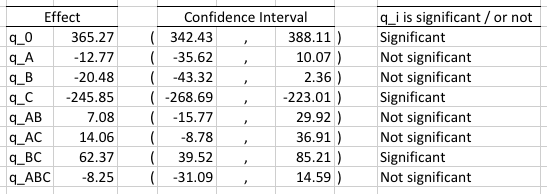
Indeed the protocol (factor C) is statistically significant and we model the system with the equation:
We interpret the model as follows. The mean latency is about 365 ms. Ignoring the small interaction, if the protocol in use is BoX-MAC then latency will increase by about 245 ms; RI-MAC will decrease the latency by 245 ms. With latency being a LB (Low Better) metric we see that RI-MAC is a much faster protocol.
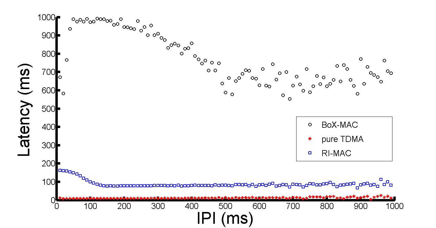
We found this finding fascinating and had to go beyond the experimental design for another short detour. We conducted 50 more fine-grained experiments comparing RI-MAC with BoX-MAC (TDMA also appears on these plots because we wanted an additional frame of reference, but you can ignore it for the class project).
The Inter-Packet Interval (IPI) is the reciprocal of the application demand for throughput. We see that for all throughput demand as our statistical modeling predicted properly: RI-MAC has lower latency (is a faster protocol).
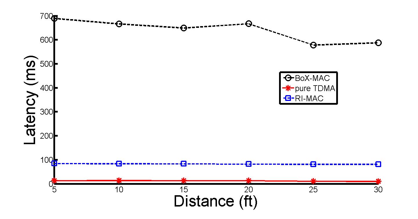
As can be seen in the next plot, varying the distance away from a WiFi access point (and hence varying the noise) does not change the conclusion, RI-MAC is superior in terms of latency across the interference levels.
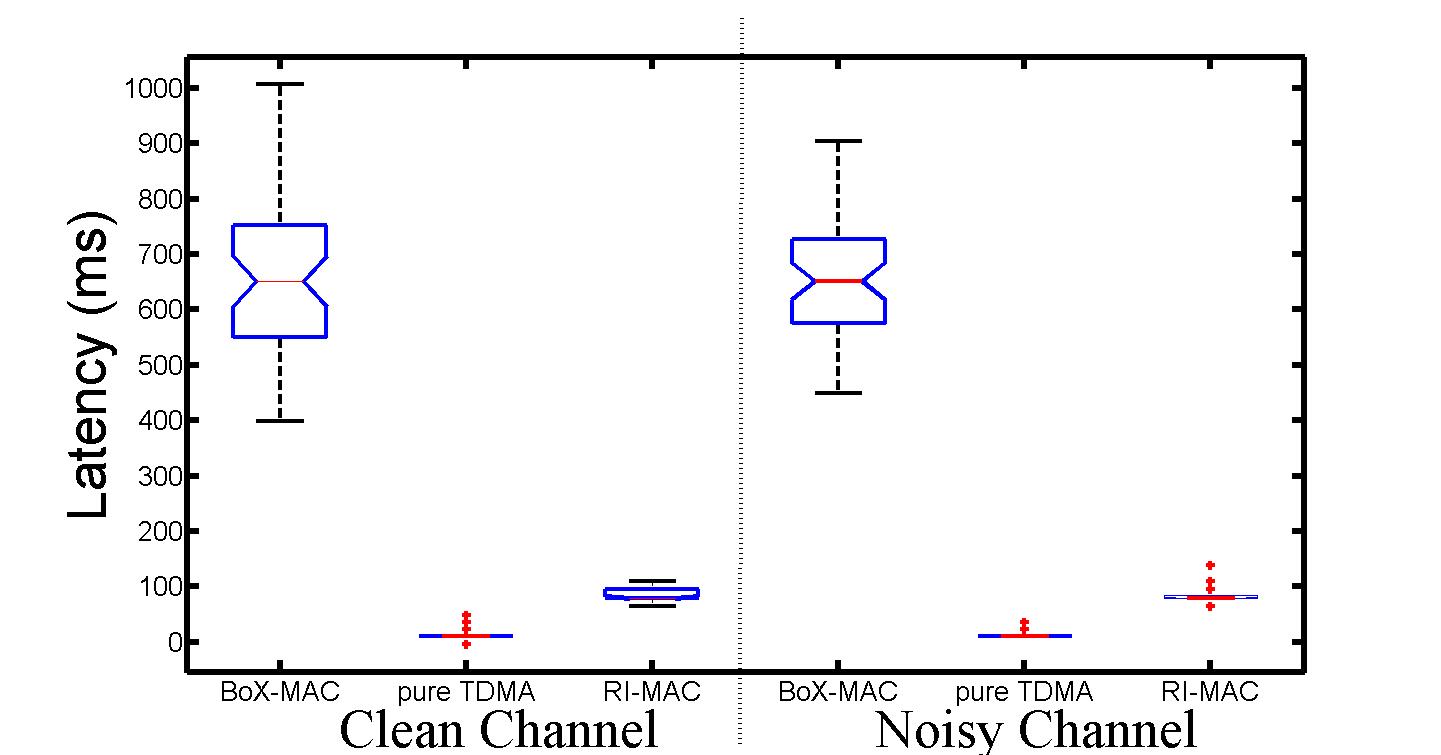
We conclude with a box and whiskers plot for the additional fifty experiments that clearly shows support for our statistical analysis model. We were also very happy to get another reassurance from this plot. As you can see on the y-axis, as predicted by our model equation (without accounting for interactions) RI-MAC will operate at around 120 ms and BoX-MAC will operate at around 600 ms.
We now return to the regular visual tests section and make sure that the model is valid. We start by verifying that the modeling assumption of independent errors is correct.
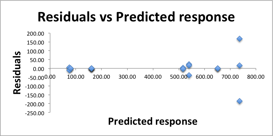
There is some worrisome range of errors at over 700 ms, but no trend in the residuals in general. Because the residuals are small compared to the predicted responses we are approve of this test for the independence of errors.
To see if the errors are normally distributed we prepare a Q-Q-plot.
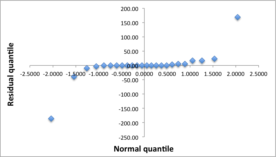
The downward and upward poll of the left and right ends of the q-q-plot suggests that the distribution is not normal. This trend, which repeated itself in all of our three designs, should be explored in the future. At this point we believe that it might related to additional factors that need to be studied or some non-linear behavior of the system at some edges of its operating knobs.
We performed three experimental designs to study the performance of MAC protocols used in Wireless Sensor Networks. All three designs led to important observations. To the extent that we understand how WSN work, these experiments also led to correct observations. This study could be the springboard to many more experimental designs that may lead to an optimization engine of a new sort (see future work section).
In these experiments we learned that a WSN mote consumes a mean of 70 mW and that the demand for low or high throughput will lower or increase, respectfully, the energy consumption by about 12 mW. The choice of protocol and the interaction between throughput demand and protocol will also vary the consumption about 12 mW each.
We learned that the mean reliability of a mote is 74% and RI-MAC is more reliable than BoX-MAC at low throughput demand, but RI-MAC should be avoided at all cost in high throughput demand were its performance completely degrades. Contrary to that, at high throughput BoX-MAC increased its reliability by 21% above the mean.
But when it comes to latency RI-MAC is a much faster protocol. The model predicts that it will perform better under all application demands (because all other factors turned out to be statistically not significant and not important). Detailed experiments, which were initially beyond the scope of our project confirmed this model.
We are planning to study more factors (for example the lack of effect of interference is surprising) in a few more 2^k r experiments and then dive into designs with more levels. Regression will also be a tool that we will use. In particular, now that we have seen how much can be achieve with these methods, we are extremely interested in comparing and contrasting the modeling power and the amount of insight that can be drawn from regression method vs. 2^k r methods.
Our final goal will be to design a classifier at the OS level that will allow application to specify their needs and let the OS optimize the protocols to accommodate it.
I would like to thank Mo Sha for his invaluable assistance with RMA, the experiments, and his protocol (and other) wisdom. I truly enjoyed being able to talk with Mo as I was working on this project. I would like thank my mentor Dr. Chenyang Lu for suggesting to evaluate WSN protocols, it turned out to be a very good insight. Last, but not least, none of this could have occurred without Dr. Raj Jain teaching. Taking his class opened my eyes to yet another way of looking at systems, only a small part of it made it to this paper. I am quite sure that these new tools would be indispensable in my future endeavors.