Figure 1.A parallel traffic replication scalable configuration
Methodology for Implementing Scalable Test Configurations in ATM Switches
Arjan Durresi ¨, Raj Jain ¨, Gojko Babic ¨, and Bruce Northcote §
¨Department of Computer and Information Science, The Ohio State University,
2015 Neil Ave, Columbus, OH 43210-1277 USA
Phone: 614-688-5610, Fax: 614-292-2911, Email:
durresi@cse.wustl.edu
§Fujitsu Network Communications
289 Great Rd, Acton, MA 01720 USA
Phone: 978-266-4594, Fax: 978-266-2300, Email: bsn@nexen.com
Abstract
In performance testing of ATM switches and network of switches a variety of connection configurations is needed. In most of the cases, these configurations require one traffic generator and/or analyzer for each switch port. Since this equipment is rather expensive, it is desirable to define scalable configurations that can be used with a limited number of generators.
In this paper we present a methodology for the implementation of scalable connection configurations. The methodology is simple and offers a general solution to generate scalable connection configurations. Several examples of scalable configurations illustrate the methodology. The application of this methodology helps users to repeat easily performance tests under the same traffic load conditions.
Keywords: ATM equipment performance testing techniques.
1. Introduction
In order to compare different ATM equipment, it is important to compare them on a set of standard configurations and workloads [1, 2, 5, 6, 7]. One problem that we run into when trying to compare ATM switches is that these switches can have a large number of ports. To test these switches at high loads, a traffic generator and analyzer may be required for each port. These generators and analyzers are expensive. It is therefore, desirable to find ways to minimize the number of such generators and analyzers. In this paper, we discuss such ways and issues related to them [3, 4, 6].
The key problem with scalable configurations is that there are many ways to set up the connections and measurement results could vary with the setup. For example, In the case of unicast, it may not be possible to overload a port with only one generator. Using two generators in scalable configurations may exhibit different behavior, such as overloading, that may not show up with one generator. The application of this methodology helps users to create easily the same traffic load for independent performance tests and make the latest more comparable.
Performance testing requires two kinds of virtual channel connections (VCCs): foreground VCCs (traffic that is measured) and background VCCs (traffic that simply interferes with the foreground traffic) [3, 4]. The methodology for generating configurations of both types of VCCs is covered by this paper.
The VCCs are formed by setting up connections between ports of the switch. The connections are internal through the switch fabric and external through some transmission medium or wires (which could be cables, fibers, or even wireless links), depending on the port technology. In this Paper, internal connections are shown by thin lines and external connections by thick lines. An arrow indicates the direction of the connection. If a connection is bi-directional, which is often the case, arrows are not used. It should be noted that whenever external connections are used in the test configurations, only permanent VCCs can be established.
Throughout the paper it is assumed, for improved readability, that the implementation under test (IUT) consists of a single ATM switch, although the methodologies presented here apply equally to test cases in which the IUT is a network of ATM switches or, alternatively, a subset of modules of a single switch. The notation Pijis used to refer to the jthport of the ithmodule of the IUT, and (Pab, Pcd) indicates that a connection (either internal or external to the IUT) exists between Paband Pcd.
Two generic categories of scalable configuration are presented in this paper, namely:

Figure 1.A parallel traffic replication scalable configuration
2. Parallel Traffic Replication
The point-to-multipoint capability of a switching system is intended primarily for broadcast communication services, but which also lends itself well to the task of generating the traffic inputs to the IUT that are required for the test configurations. Identical ATM cells are broadcast in parallel from multiple output ports – hence ‘parallel traffic replication’. Given a single traffic generator, and a switching system (other than the IUT) with a point-to-multipoint capability (a multicast switch), an IUT may receive traffic on as many input ports as the multicast switch has available output ports. This form of scalable configuration is depicted in Figure 1, where G is the single traffic generator. Internal to the IUT, any of the configurations specified in [1] may be used.
The weakness of this solution is that the measurement may be influenced by the performance of the multicast switch. Also if the multicast switch does not support multipoint-to-point connections, then this form of parallel traffic replication cannot support bi-directional connection configurations. In such cases and when the influence of the multicast switch performance in the measurement is not desirable, it may be necessary to use serial traffic replication, as described in the next section.
3. Serial Traffic Replication
An example test configuration employing serial traffic replication is provided in Figure 2, which shows a 4-port switch with ports labeled as P11,P12, P21and P22. Of these, ports P21and P12are connected by a wire W1, while port P22has a "loopback" wire LB that connects the output of the port to its input. Internally, a PVC has been set up to connect ports P11with P21and P12 with P22. Note that all external connections (wires) and internal connections (PVCs) in this case are bi-directional, except the loopback. During testing with this configuration, cells first enter the switch at P11and are passed through every port of the switch in series, before looping back at P22and following the reverse path back to exit the switch for the last time at P11.
The methodology presented here has two phases. During the first phase the switch ports are connected externally by numbered wires, as in Section 3.1. The second phase consists of setting up PVCs, i.e. internal connections between ports, as explained in Section 3.2.
The sequence of concatenated connections (internal and external) is called a VCC Chain. For example, the VCC shown in Figure 2.b. is formed by setting up a VCC chain starting from P11-In. ATM cells flow internally from P11-In to P21-Out, externally via wire W1to P12-In, internally to P22-Out, externally via wire LB to P22-In, internally to P12-Out, externally through wire W1to P21-In, finally exiting at P11-Out. This VCC chain can be indicated as:
Generator-P11-P21-P12-P22-P22-P12-P21-P11-Analyzer.
Of these connections, P22-P22is a unidirectional external connection (loopback, denoted as LB) and P12-P21is a bi-directional external connection (wire, denoted as W). All of the internal connections (VCCs) are bi-directional. The sequence of external connections used in this VCC chain is: Generator-W1-LB-W1-Analyzer.

a) Representation of physical switch b) Logical representation of the switch and its port connections
Figure 2.A VCC chain that can implement the 4–to-4 straight configuration
Both the above notations are symmetric in the sense that the second half of the chain is a mirror image of the first half. For example, W1-LB is the mirror image of LB-W1.
Another possible configuration for this "n-to-n single generator scalable configuration" is P11-P12-P21-P22-P22-P21-P12-P11.
The various VCC chains may be distinguished by the order of, and the direction through which, each wire is initially traversed by the generated traffic.
The four-port switch shown in Figure 2 consists of two modules with two ports each. The measured performance for a given test configuration may depend upon whether the internal connections of the VCC chain are inter-module, intra-module, or a mixture of both. The methodology presented in this paper ensures that it is possible for exclusively inter-module, or intra-module traffic to be carried.

Figure 3.Example partitioning of modules into groups.
3.1. Implementation of External Connections
The methodology for implementing the external connections consists of the following three steps:
These steps are now explained.
Step 1. Identifying the modules to be included in the IUT
In order to ensure that it is possible for the configuration to support exclusively inter-module and/or intra-module internal connections, the IUT should consist of pairs of similar modules. If this constraint is not satisfied, the VCCs that are established may be a mixture of inter-module and intra-module connections. It is not necessary that the modules/ports be labeled, although we use the Pijformat here to assist in the description of the methodology.
Consider a switch with several modules of different port types. The ports could be different in speed and/or connector type. Each module may have a different number of ports. For example, a switch may have two modules of eight and six 155-Mbps single-mode fiber ports, respectively, another module with eight 155-Mpbs UTP ports and a fourth module with six 25-Mbps UTP ports. Figure 3 shows an example IUT where the modules are grouped by type. The first group consists of two 25-Mbps UTP modules, the second group consists of two 155-Mbps single fiber modules.
External connections may only be established between ports that are co-located within the same group (hence the constraint that modules come in pairs for inter-module connectivity).
Step 2. Connect the generators and analyzers to appropriate ports
A port must be reserved for each generator/analyzer that is to be used in the test. These reserved ports cannot be used in the next step that establishes external connections. The methodology presented here allows any given number, r<n, of generators. Some additional constraints on the number of ports in the IUT are explained in the next step.
Step 3. Establish and number external connections
After selecting the ports that are reserved for connection to generators/analyzers, the remaining ports have to be externally connected with numbered "wires". The following guidelines should be followed when establishing the wires:

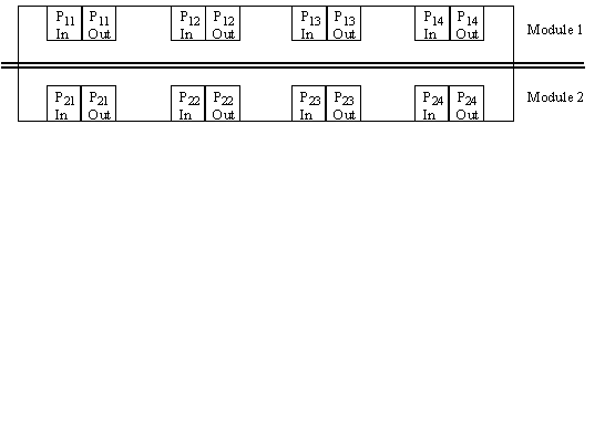
Figure 4.a.Port labeling of the example switch (2 modules of 4 ports each).

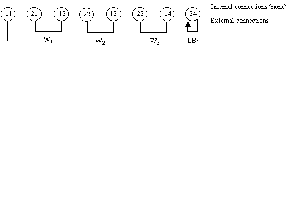
Figure 4.b.Wiring configuration for the example switch.
The following example illustrates the methodology for establishing the wires:
Consider the n-to-n straight configuration required for the foreground traffic in throughput measurement. Suppose the switch has two modules with four ports each of the same speed and connection type. The ports are labeled as shown in Figure 4.a. P11is arbitrarily selected to be connected to the single generator/analyzer that is to be used. There will only be one subgroup, because there is only one generator/analyzer and all the ports are of the same speed and connection type. The non-reserved ports in the subgroup are {P12, P13, P14, P21, P22, P23, P24}. The wires W1=(P12, P21), W2=(P13, P22) and W3=(P14, P23) are obtained by alternatively selecting ports of the first and second module from the non-reserved list of ports. Finally, the loopback is placed at the remaining port, namely P24. Figure 4.b shows the resulting wiring configuration. Note that it will allow for either exclusively inter-module, or exclusively intra-module traffic (this will be shown in the next section).
3.2. Implementation of Internal Connections
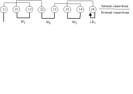
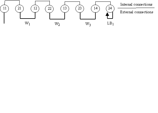
The methodology presented in this paper can ensure that exclusively inter-module or intra-modules traffic is carried, depending on the implementation of the internal connections. For example, Figures 4.a and 4.b show configurations for intra-module and inter-module configurations, respectively, although both are based on the wiring indicated in Figure 4.b.
As indicated earlier, VCC chains may be distinguished by the order of, and the direction through which, each wire is initially traversed by the generated traffic. We only consider VCC chains that use every non-reserved port within a single subgroup. Using the same terminology as in Section 3.1, assume that we have established x wires and a single loopback for a subgroup with m non-reserved ports, and r generators. For a given traffic flow (intra-module or inter-module), a VCC chain that passes through each non-reserved port can be expressed as:
generator – ‘x wires in series’ – LB – ‘x wires in reverse series’ – analyzer.
Stated more succinctly, the VCC chain only depends on the generator/analyzer used and the ordering of the ‘x wires in series’. The example in Figure 5 used the ordering W1W2W3. For a given traffic generator and wire ordering there exists a unique set of VCCs that provides an intra-module VCC chain. Similarly for an inter-module VCC chain.

Figure 5.a.An 8-to-8 straight configuration for the example switch using intra-module VCCs.

Figure 5.b.An 8-to-8 straight configuration for the example switch using inter-module VCCs.
Establish the bi-directional internal connection Vx+1= (Pin, PLB). The VCC chain is now fully specified as:
generator-V1-W1-V2-W2- … -Wx-Vx+1-LB-Vx+1-Wx- … -W2-V2-W1-V1-analyzer.
Clearly, if any other wire ordering, or any other generator (out of the r generators assigned to the subgroup) was used, a different VCC chain would have resulted.
Referring again to the example provided in Figures 4.a and 4.b, only one VCC chain is established for each traffic flow. In the case of an n-to-m partial cross configuration with a single generator, several VCC chains are required, each based on a different ordering of the same subgroup of wires. The six (3!) possible permutations for the example are: W1W2W3, W2W3W1, W3W1W2, W3W2W1, W2W1W3and W1W3W2, each of which would result in a distinct VCC chain for the single generator.
The examples given in Section 3.4 illustrate the ways in which multiple VCC chains and/or multiple generators may be used in serial traffic replication scalable configurations.
3.3. Background Traffic
To establish a configuration that incorporates background test traffic, the background traffic may:
To implement a configuration with background traffic, one or more ports need to be reserved for foreground traffic. Therefore, to implement:
Case 1 (distinct ingress and egress) – reserve 2 ports for each foreground traffic stream.
Cases 2 & 3 (shared ingress or egress) – reserve 1 port per foreground traffic stream.
3.4. Examples of scalable connection configurations
In this section, several examples of scalable connection configurations are provided. In all of the examples, a switch with two 4-port modules is used (as in Figure 4.a), where all ports are of the same speed and connector type.
3.4.1. n-to-n Straight (Single Generator)
This configuration may be used for throughput as well as latency measurements. Suitable test configurations that employ serial traffic replication can be obtained as follows:
a) Foreground traffic (Throughput measurements)
For these tests, only a single chain starting from a single generator is needed. Figures 4.a and 4.b, provide adequate examples of this type of connection configuration.
b) Background traffic (Latency Measurements)
In this example, the background traffic does not use the input/output ports of the foreground traffic. As shown in Figure 6, generator/analyzer G1is used for background traffic while generator/analyzer G2is used for foreground traffic.
The background traffic passes through each port not assigned to the foreground traffic. Inter-module external connections are established by following the guidelines described in Section 3.1, resulting in wires W1, W2, and LB1. The VCC chain of the background traffic corresponds to the wire ordering W1W2. So the VCC chain is given by :
G1-V1-W1-V2-W2-V3-LB1-V3-W2-V2-W1-V1-G1, where,
by establishing exclusively inter-module VCCs: V1= (P12, P22), V2= (P13, P23), V3= (P14, P24).
3.4.2. n-to-n Straight (r Generators)
Foreground traffic
To realize an n-to-n straight configuration with r generators, we need to design r VCC chains. Of the n ports, r ports are used as the source/destination of these chains. The remaining ports are connected among themselves and their wires are divided in subgroups among the generators ensuring an odd number of ports in each subgroup.
As an example, consider the 8-port switch again, with r = 3 generators. In dividing the available ports in three subgroups the goal is to have an odd number of ports in each subgroup. The partitioning of ports into subgroups results in one subgroup with three ports and two with one port each. The three ports subgroup is used by the first generator. Note that the wiring configurations of the other two subgroups consist only of a single loopback. Figure 7 illustrates the implementation of the VCC chains for this case. First we select the source and destination ports. Let, P11be the input/output port for the first chain, P21be the input/output port for the second chain, and P12be the input/output port for the third chain. Using only intra-module VCCs the following VCC chains are obtained:
G1-V1-W1-LB1-W1-V1-G1,
G2-V2- LB2-V2-G 2, and
G3-V3- LB3-V3-G3, where
V1= (P11, P13), V2= (P21, P24) and V3= (P12, P14).

Figure 6.The 6-to-6 straight configuration with one generator using inter-module VCCs, where the foreground traffic does not share any port with the background traffic.

Figure 7.Implementation of the 8-to-8 straight configuration with 3 generators using intra-module VCCs.

Figure 8.Implementation of 8-to-2 partial cross configuration with 2 generators for foreground traffic using intra-module VCCs.
3.4.3. n-to-m Partial Cross (r Generators)
This configuration has m*r VCC chains starting from rgenerators,where each generator originates m VCC chains. Each chain has a load of 1/mthof the traffic egressing from the generator. Each intermediate wire has exactly m of these streams flowing through it. There are r subgroups and the switch ports, other than those reserved to be connected to the r generators, are divided among them.
a) Foreground traffic: 8-to-2 (m=2) partial cross configuration with 2 generators (r=2).
For the configuration example shown in Figure 8, there are two subgroups (one for each generator) with three ports each.
The following intra-module VCC chains form the required test configuration:
G1-V1-W1-V2-LB1-V2-W1-V1-G1,
G2-V3-W2-V4-LB2-V4-W2-V3-G2,
G1-V5-W1-V6-LB1-V6-W1-V5-G1, and
G2-V7-W2-V8-LB2-V8-W2-V7-G2 , where
V1= (P11, P13), V2= (P21, P23), V3= (P12, P14), V4= (P22, P24), V5= (P11, P14), V6= (P22, P24),
V7= (P12, P13), and V8= (P21, P23).
b) Foreground traffic: 8-to-3 partial cross with one generator
This case is illustrated in Figure 9. There is only one subgroup composed of wires W1, W2, W3. The three VCC chains required for this test configuration (each constructed from a distinct wire ordering, with inter-module VCCs) are:
generator-V1-W1-V2-W2-V3-W3-V4-LB1-V4-W3-V3-W2-V2-W1-V1-analyzer,
generator-V5-W2-V6-W3-V7-W1-V8-LB1-V8-W1-V7-W3-V6-W2-V5-analyzer, and
generator-V9-W3-V10-W1-V11-W2-V12-LB1-V12-W2-V11-W1-V 10-W3-V9-analyzer,
where for tests involving exclusively inter-module traffic, the VCCs are:
V1= (P11, P21), V2= (P12, P22), V3= (P13, P23), V4= (P14, P24), V5= (P11, P22), V6= (P13, P23),
V7= (P14, P21), V8= (P12, P24), V9= (P11, P23), V10= (P14, P21), V11= (P12, P22), V12= (P13, P24).

Figure 9. 8-to-3 partial cross with one generator using inter-module VCCs
4. Conclusion
We have presented a methodology for the implementation of scalable test configurations in ATM switches. The methodology is simple and offers a general solution to the problem of scalable configurations in ATM switches. The application of this methodology helps users to repeat easily performance tests under the same traffic load conditions and therefore independent performance tests will result more comparable.
5. References:
[1] ATM Forum/BTD-TEST-TM-PERF.00.10 (Draft) December 1998
[2] Arjan Durresi, Raj Jain, Gojko Babic, and Bruce Northcote, Proposed modified text for Methodology for Implementing Scalable Test Configurations, ATM_Forum/98-0410, July 1998, http://www.cse.wustl.edu/~jain/atmf/atm98-0410.htm
[3] Raj Jain and Gojko Babic, Performance Testing Effort at the ATM Forum: An Overview, IEEE Communication Magazine, Special issue on ATM performance, August 1997, 11 pp., http://www.cse.wustl.edu/~jain/papers/perf_com.htm
[4] Arjan Durresi, Raj Jain, Justin Dolske, Gojko Babic, Modifications to Appendix B and Sections 3.1.7 and 3.2.7 of Performance Testing Baseline Text. ATM Forum/97-1089, December 1997, http://www.cse.wustl.edu/~jain/atmf/atm97-1089.htm
[5] Arjan Durresi, Raj Jain, Justin Dolske, Gojko Babic, Proposed Appendix B of Performance Testing Baseline Text on Scalable Configurations, ATM Forum/97-0835, September 1997 http://www.cse.wustl.edu/~jain/atmf/atm97-0835.htm
[6] Gojko Babic, Arjan Durresi, Justin Dolske, Raj Jain, Measurement Experiences with the Revised MIMO Latency Definition, ATM Forum/97-0859, September 1997 http://www.cse.wustl.edu/~jain/atmf/atm97-0859.htm
[7] Gojko Babic, Arjan Durresi, Raj Jain, Justin Dolske, Shabbir Shahpurwala, Proposed modifications to Performance Testing Baseline Text, ATM Forum/97-0426, April 1997 http://www.cse.wustl.edu/~jain/atmf/atm97-0426.htm